

Posted inGATE Q & A
SECTION-5 (Q/A)
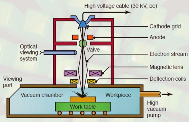
1. State the working principle of EBM? When the high velocity beam of electrons strike the workpiece, its kinetic energy is converted into heat. This concentrated heat raises the temperature of work material and vaporizes a small amount of it, resulting in removal of metal from the work piece. 2. List any two advantages of EBM? a. Very small holes can be machined in any type of material to high accuracy. b. It is a quicker process. Harder materials can also be machined at a faster rate than conventional machining. 3. What are the limitations of EBM? a. The metal removal rate is very slow. b. It is not suitable for large work pieces. c. Cost of equipment is very high d. A little taper produced on hole. e. It is applicable only for thin materials. 4. State the principle of LBM?…