
A bicycle crank snaps after years of ordinary pedaling. A rotating pump shaft develops a crack near its keyway. A bridge detail that looked sound during inspection suddenly needs repair. In each case, the part may have carried loads far below the metal’s published tensile strength.
This can seem contradictory at first. If a steel component is rated to withstand a large pull, why can a much smaller repeated force eventually break it? The answer is fatigue: progressive damage caused by repeated or fluctuating stress.
Fatigue failure matters because most machines do not experience one dramatic load. They experience thousands, millions, or billions of routine cycles: starts and stops, vibration, bending, pressure pulses, thermal expansion, and changing torque.
Understanding fatigue changes how engineers think about “strength.” A safe design is not simply one that survives the largest expected load once. It must also resist the small, repeated events that quietly create and grow cracks over time.
🔍 What Fatigue Failure Actually Means
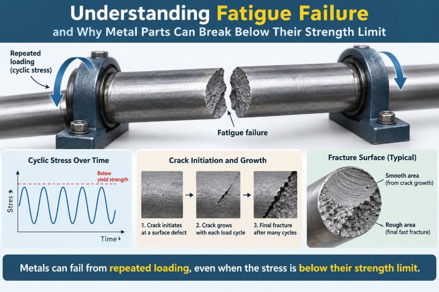
Fatigue failure is fracture caused by repeated or varying stresses. The applied stress can be well below the material’s yield strength, which is the point where permanent deformation begins under a monotonic, steadily increasing load.
The damage usually begins at a small local imperfection, then advances a little with each load cycle. Once the remaining intact material can no longer carry the load, the final fracture can occur very quickly.
Fatigue is therefore a process, not a single event. The last break may be sudden, but the conditions that enabled it often existed for a long time.
📉 Why Tensile Strength Is Not Enough
Tensile strength is commonly measured by pulling a specimen until it fractures in a relatively short test. This value is useful, but it describes resistance to a one-time overload, not necessarily resistance to millions of load reversals.
A paperclip illustrates the distinction. It can survive a modest straight pull, yet repeated bending in the same location will eventually make it break. The bending stress is concentrated at the fold and changes direction each time.
Designers must therefore consider both static strength and fatigue strength. A component can satisfy a static calculation and still have inadequate service life.
🔄 The Meaning of a Load Cycle
A load cycle is one complete fluctuation in stress. For a rotating shaft under a stationary transverse load, a point on the shaft surface moves from tension to compression once per revolution, creating a fully reversed bending cycle.
Not every cycle reverses direction. A pressure vessel may repeatedly go from zero pressure to high pressure, creating a pulsating tensile stress. A bolted joint can see a steady preload plus a smaller fluctuating load.
What matters is the stress history at the critical location, rather than simply the number of times a machine is switched on.
📊 Stress Range, Mean Stress, and Amplitude
Engineers describe fluctuating stress using a few related quantities. If the maximum stress is σmax and the minimum is σmin, the stress range is σmax − σmin.
The stress amplitude is half that range, while the mean stress is the average of the maximum and minimum stresses. A high tensile mean stress generally makes fatigue cracking more likely because the crack remains more open during cycling.
| Stress condition | Typical description | Fatigue implication |
|---|---|---|
| Fully reversed | Equal tension and compression | High alternating damage potential |
| Pulsating tension | Stress varies from near zero to tension | Tensile mean stress can accelerate crack growth |
| Steady stress | Little or no fluctuation | Usually governed more by static strength or creep |
This distinction explains why two parts with the same peak stress can have very different fatigue lives.
🧪 The Three Stages of Fatigue Damage
Fatigue is often described in three broad stages: crack initiation, stable crack propagation, and final fracture. The exact boundary between stages depends on the material, geometry, loading, and environment.
🌱 Crack initiation
A microscopic crack forms at a local region of high stress, frequently at a surface feature. This stage can consume much of the life of a smooth, well-finished component.
📈 Crack propagation and final rupture
The crack grows incrementally under repeated loading. Eventually, the remaining uncracked cross-section becomes too small, and the part fails in a final overload that may look quite different from the earlier fatigue region.
🧬 What Happens Near the Crack Tip
At a crack tip, stress is not distributed uniformly. The sharp geometry causes a strong local concentration of stress, and microscopic plastic deformation may occur even when the average stress in the part is nominally elastic.
Repeated loading advances the crack through this highly stressed zone. The mechanisms differ among metals and conditions, but the practical result is similar: a small crack can become a progressively more serious defect.
This is why fatigue design and inspection focus so strongly on finding or avoiding cracks while they are small.
📍 Stress Concentrations Start Many Problems
A stress concentration is a local rise in stress caused by geometry. Holes, sharp corners, threads, grooves, keyways, splines, and abrupt changes in thickness interrupt the smooth flow of force through a part.
Imagine water flowing around a rock. The stream changes direction and speeds up locally. Mechanical stress behaves differently in detail, but the analogy helps: force paths crowd around discontinuities.
A nominal bending stress that appears harmless on a simple beam calculation may become damaging at the root of a sharp notch.
🌀 Notches, Fillets, and Geometric Transitions
Sharp internal corners are especially unfavorable in fatigue-loaded parts. A generous fillet radius can reduce the local stress concentration by allowing the load path to turn more gradually.
The improvement is not unlimited. The benefit depends on the surrounding geometry, material sensitivity, manufacturing method, and whether the surface is damaged. Still, avoiding unnecessary abrupt transitions is one of the most dependable fatigue-design habits.
- Use smooth changes in section thickness.
- Place grooves and holes away from highly stressed regions when possible.
- Specify practical fillet radii rather than leaving corners unnecessarily sharp.
- Consider the full feature geometry, not only a nominal diameter.
🧵 Why Surface Condition Has Outsized Influence
Many fatigue cracks begin at the surface because that is where bending and torsional stresses are often highest. Scratches, machining marks, corrosion pits, dents, and handling damage can all act as small notches.
A polished laboratory specimen can show better fatigue performance than a rough production part made from the same alloy. This does not make published material data useless; it means the data must be adjusted or selected to match realistic component conditions.
Surface protection and careful finishing matter most where cyclic stress is high, not necessarily everywhere on the part.
🔥 Residual Stress Can Help or Harm
Residual stress remains in a component after manufacturing even when no external load is applied. Welding, machining, forming, heat treatment, and surface treatments can all create it.
Tensile residual stress near a surface can be harmful because it adds to service tension. Compressive residual stress can be beneficial because it makes it harder for a surface crack to open during part of the cycle.
Processes such as shot peening are used in suitable applications to introduce beneficial compressive surface stress. Their value depends on controlled processing; poor coverage, excessive intensity, or later grinding can reduce the intended benefit.
⚗️ Material Microstructure Matters
Grain size, inclusions, phases, heat treatment, and cleanliness influence how a metal initiates and resists fatigue cracks. Two steels with similar static strength can behave differently because their microstructures and defect populations differ.
Higher strength is not automatically a complete fatigue solution. Some high-strength materials are more sensitive to notches, surface damage, hydrogen exposure, or manufacturing defects. Selection must balance strength, toughness, corrosion resistance, manufacturability, and expected loading.
Material data should also match the product form: forged, rolled, cast, welded, and additively manufactured parts can have different relevant characteristics.
📈 Reading an S–N Curve
An S–N curve, also called a stress-life curve, plots stress amplitude against the number of cycles to failure. It is built from fatigue testing of specimens under defined conditions.
In general, higher stress amplitudes cause failure in fewer cycles. As the applied alternating stress falls, the expected life increases, sometimes substantially.
These curves are statistical in nature. Real components differ from test specimens in surface finish, size, environment, residual stress, and geometry. A responsible design process applies appropriate corrections, safety factors, and validation rather than treating a single curve as an absolute promise.
♾️ Endurance Limit and Its Limitations
Some ferrous alloys are often treated as having an endurance limit: below a certain stress amplitude under particular test conditions, they may survive a very large number of cycles without observed failure.
Many nonferrous alloys, including common aluminum alloys, do not show such a clear horizontal limit in typical S–N data. Their fatigue strength is often specified at a chosen number of cycles instead.
Neither concept removes the need for caution. Corrosion, fretting, overloads, and manufacturing variation can reduce real-world fatigue resistance even when nominal stress appears low.
⏳ High-Cycle and Low-Cycle Fatigue
High-cycle fatigue generally involves many cycles with stresses that are mostly elastic at the nominal level. Rotating shafts, fans, and vibration-sensitive brackets are common examples.
Low-cycle fatigue involves fewer cycles but significant local plastic strain. Thermal cycling in engine components or repeated large deflections in a formed metal part may fall into this category.
The labels are useful, but the physical distinction matters more than a fixed cycle count. Stress-life methods are commonly used for predominantly elastic conditions, while strain-life methods are often more appropriate when local yielding is expected.
🌡️ Thermal Cycling Is Mechanical Cycling
Temperature changes make materials expand and contract. If that movement is restrained by a joint, support, or neighboring component, thermal stress develops even when no one is applying an obvious mechanical force.
Exhaust systems, heat exchangers, electronic packages, piping, and engine parts can experience fatigue from repeated heating and cooling. Differences in thermal expansion between joined materials can intensify the problem.
Providing flexibility through expansion loops, compliant features, or suitable joint design can be as important as choosing a heat-resistant alloy.
🌊 Corrosion Fatigue Changes the Design Picture
In a corrosive environment, cyclic loading and chemical attack can work together. Corrosion pits create stress raisers, while repeated stress can damage protective films and promote crack advance.
This is called corrosion fatigue. A component that performs acceptably in dry laboratory air may have a shorter life in salt spray, humid service, process chemicals, or marine exposure.
Coatings, drainage, sealing, material selection, and inspection are useful controls, but each must suit the environment. A damaged coating that traps moisture in a crevice can create a different problem rather than solving the original one.
🤝 Fretting Fatigue at Contact Interfaces
Fretting occurs when two contacting surfaces undergo very small repeated relative motions. The motion can damage the surface, create wear debris, and produce local stress concentrations.
It commonly appears in bolted joints, splines, press fits, bearing seats, and clamped interfaces exposed to vibration. A dark reddish-brown debris on steel interfaces can be a clue, though visual evidence alone is not a full diagnosis.
Controlling contact pressure, fit, surface treatment, preload, and vibration can reduce fretting risk. Lubrication may help in some designs but is not universally compatible with every joint or environment.
🔩 Welds Need Special Fatigue Attention
Welded structures often contain geometric transitions at weld toes, possible undercut, residual tensile stress, and variation in local quality. These features make fatigue assessment more complex than checking the base-metal strength alone.
A smooth weld profile and sound fabrication practice can improve performance. However, simply specifying a stronger base metal does not necessarily improve the fatigue category of a welded detail if the weld geometry remains the governing feature.
Designers should also avoid placing welds directly in peak-stress zones when the layout permits it. Inspection plans should reflect the consequence of a crack at each critical joint.
🧱 Castings, Porosity, and Internal Defects
Cast components can be excellent engineering solutions, especially where complex geometry is valuable. Yet pores, shrinkage regions, inclusions, and surface irregularities may reduce fatigue performance if they occur in highly stressed locations.
The relevant question is not whether a casting has any imperfection, but whether defect type, size, location, and orientation are acceptable for the expected load history. Process control and nondestructive examination can be targeted to critical areas.
Designing a casting with smooth load paths and adequate section transitions helps reduce sensitivity to unavoidable manufacturing variation.
🚗 Everyday Examples of Fatigue Loading
Automotive suspension components see road-induced cycles over varied amplitudes. A ceiling fan shaft experiences rotating bending. An aircraft wing undergoes changing lift loads during service. A hand tool flexes at its handle-to-head transition.
These examples differ in consequence and regulation, but they share a principle: the load is variable, and the critical damage may be localized. The largest visible force is not always the most informative predictor of life.
For a hypothetical bicycle component, a small gouge near a pedal-thread transition can matter more than a slightly higher overall rider load applied to a smooth, undamaged section.
🕵️ Recognizing the Appearance of a Fatigue Fracture
A fracture surface can sometimes reveal valuable clues. Fatigue regions may appear smoother than the final overload region because the crack advanced gradually before the remaining ligament broke suddenly.
Under favorable conditions, marks associated with changing crack-front positions may be visible. Their presence, absence, or appearance depends on material, loading, surface condition, and the scale of examination.
Fracture appearance should be interpreted carefully. Cleaning, corrosion, post-failure rubbing, and secondary damage can obscure evidence. A proper failure analysis considers the entire component, loading history, and manufacturing record.
🧰 Inspection Methods Find Different Things
No single inspection technique finds every fatigue crack. The best method depends on material, geometry, access, expected crack orientation, surface condition, and the smallest defect that must be detected.
- Visual inspection can reveal deformation, corrosion, rubbing, and obvious cracking.
- Dye penetrant testing is useful for surface-breaking cracks in suitable nonporous materials.
- Magnetic particle inspection can reveal near-surface discontinuities in ferromagnetic materials.
- Ultrasonic testing can detect internal flaws or crack-like features when geometry and access allow.
- Eddy-current testing is often effective for near-surface defects in conductive materials.
Inspection is most effective when it is planned around credible crack locations, not used as a substitute for understanding the design.
📐 Designing for Fatigue Resistance
Good fatigue design begins with a realistic load spectrum: not only the maximum load, but its frequency, sequence, mean stress, vibration content, and likely misuse. Measurements from prototypes or operating equipment can be valuable where assumptions are uncertain.
Next, designers reduce local stress through geometry, choose materials and finishes suited to service, and consider environmental protection. They also account for assembly effects such as bolt preload, alignment, and contact conditions.
A robust component usually combines several modest improvements rather than relying on one dramatic change. A larger fillet, better surface finish, reduced vibration, and improved drainage can collectively create a meaningful margin.
🧮 Variable-Amplitude Loading and Damage Accumulation
Real loading rarely repeats at one perfectly constant amplitude. A truck bracket sees smooth-road vibration, pothole events, braking loads, and occasional overloads. The order and interaction of these events can matter.
Engineers often use cumulative-damage approaches to estimate the effect of a load spectrum. A familiar simplified method adds fractions of life used at each stress level, but it has limitations and may not capture all sequence effects.
Such calculations are useful engineering tools, not guarantees. When failure consequences are high, testing, conservative assumptions, and damage-tolerant design may be needed alongside analytical life estimates.
🛡️ Safe-Life and Damage-Tolerant Strategies
A safe-life approach replaces a part before a calculated or demonstrated life is consumed. This can be appropriate when reliable inspection is difficult or when a small crack could rapidly become unacceptable.
A damage-tolerant approach assumes flaws may exist and seeks to ensure that cracks grow slowly enough to be detected before reaching a critical size. It relies on fracture mechanics, inspection capability, and controlled operating assumptions.
Neither strategy is automatically superior. The right choice depends on accessibility, redundancy, consequences of failure, inspection reliability, cost, and how predictable the loading is.
⚠️ Common Fatigue Design Mistakes
Several errors repeatedly lead to disappointing fatigue performance:
- Checking only yield strength or ultimate tensile strength.
- Using polished-specimen data without considering actual surface finish and size.
- Ignoring tensile mean stress, preload changes, or residual stress.
- Adding a hole, thread, weld, or sharp transition late in the design process.
- Assuming vibration loads are negligible because displacement looks small.
- Neglecting corrosion, fretting, or thermal cycling in the service environment.
These are often system-level mistakes rather than calculation mistakes. The component may be analyzed carefully, but under an unrealistic picture of how it will be made and used.
🔧 What Maintenance Teams Can Do
Maintenance cannot eliminate every fatigue risk, but it can prevent a small issue from becoming a fracture. Recurrent inspection should focus on known high-stress regions, attachment points, weld toes, holes, and locations with corrosion or wear.
Documenting crack location and direction is especially useful. Replacing a broken part without understanding why it cracked can lead to repeated failures, particularly if the replacement has the same geometry and operating conditions.
Changes in vibration, noise, alignment, load, or cycling frequency deserve attention because they can alter fatigue demand without any obvious change in average operating performance.
🧑🔬 Why Testing Still Matters
Analysis can identify critical regions and compare design options, but fatigue contains uncertainty. Material variation, assembly scatter, surface condition, environmental exposure, and unanticipated vibration can all affect service life.
Prototype testing helps reveal whether the assumed load paths and boundary conditions are realistic. Strain gauges, accelerometers, crack monitoring, and teardown inspection can turn a vague concern into measurable design information.
Testing should represent the intended component and service conditions as closely as practical. An accelerated test is useful only when the acceleration does not change the dominant failure mechanism in a misleading way.
🧭 A Practical Fatigue Investigation Sequence
When a metal part breaks unexpectedly, a disciplined sequence reduces guesswork:
- Preserve the fracture surfaces and document the as-found condition.
- Identify the likely crack origin and map nearby geometric features.
- Review loads, duty cycle, vibration, temperature, environment, and recent changes.
- Check material, heat treatment, manufacturing records, and assembly conditions.
- Compare observed damage with plausible fatigue, overload, corrosion, or wear mechanisms.
- Correct the root contributors before returning the system to service.
The goal is not merely to name the failure mode. It is to identify the conditions that allowed initiation and growth.
🧠 The Core Principle Behind Fatigue Failure
Metal parts do not have one universal “strength” value that applies to every situation. Their resistance to failure depends on stress level, number of cycles, stress concentration, surface condition, mean stress, material state, environment, and the presence of defects.
A low nominal stress can be severe when it repeats at a notch for a long time. Conversely, a relatively high one-time load may be acceptable if it stays below the relevant static limits. Context determines which failure mode governs.
The most useful habit is to ask: where is stress concentrated, how does it fluctuate, and what could initiate a crack there? That question leads naturally to better geometry, better manufacturing control, better inspection, and more reliable machines.
Fatigue failure is not a contradiction of material strength; it is evidence that repeated loading, local conditions, and time must be designed for together. ⚙️🔍🛠️