
A maintenance technician opens a pump housing and finds the familiar problem: a cracked component that is difficult to replace, expensive to machine, and unavailable for weeks. The part looks simple from the outside, but inside it contains curved passages, mounting features, and surfaces that must align precisely with seals and bearings.
For decades, the likely response was to redesign the housing for casting or machining, assemble several simpler pieces, or wait for a replacement from the original supplier. Each option solves one problem while introducing another: longer lead time, more joints, extra mass, or less efficient flow.
Additive manufacturing changes the starting question. Instead of asking, “How can this part be cut from a block or removed from a mold?” engineers can ask, “What shape best performs the job?”
That shift does not make conventional manufacturing obsolete. It does, however, give mechanical engineers a powerful way to rethink complex machine parts—especially where internal geometry, low production volume, part consolidation, or rapid iteration matters.
🧱 What Additive Manufacturing Actually Means
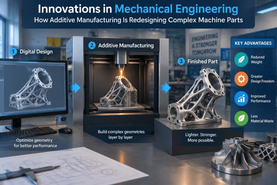
Additive manufacturing is the controlled creation of a three-dimensional object by adding material layer by layer from digital design data. It is often called 3D printing, although the industrial term covers far more than desktop plastic printers.
For machine parts, the feedstock may be metal powder, metal wire, polymer filament, liquid resin, or a polymer powder. A machine selectively fuses, deposits, or cures this material until the final shape is built.
The defining contrast is with subtractive manufacturing. Machining starts with a billet, plate, or casting and removes material. Additive manufacturing places material mainly where the design needs it, though finishing operations are still common.
🔄 Why Complex Parts Challenge Traditional Processes
Traditional processes have built modern industry for good reasons: they can be fast, accurate, and economical at scale. Yet every process has geometric rules. Cutting tools need access; casting patterns need draft and cores; molds need to open; weldments need joints and fixturing.
Those rules often influence a design as much as the part’s function. A fluid manifold may be split into several drilled blocks because a conventional drill cannot follow a curved internal channel. A bracket may remain bulky because removing material would require inaccessible machining.
Additive processes relax some of these constraints. They do not eliminate constraints; they replace them with different ones involving build orientation, support structures, heat flow, powder removal, and post-processing.
🧠 Design Freedom Is Not Design Without Rules
A common misconception is that an additive machine can make any imaginable geometry. In practice, printable geometry depends on the material, process, machine, orientation, and required quality.
Overhangs may need temporary supports. Enclosed cavities may trap unfused powder. Thin walls can distort under thermal stress, and internal channels must be large enough to clean and inspect. Good additive design works with these realities from the first concept sketch.
Design freedom is valuable only when it is paired with manufacturing discipline. A striking shape that cannot be built repeatably, finished, or verified is not an engineering solution.
🧰 The Main Metal Additive Processes
Mechanical engineers will encounter several metal additive manufacturing routes. Their names vary by supplier, but their working principles are more useful than brand labels.
Powder-bed fusion
In powder-bed fusion, a thin layer of metal powder is spread across a build plate. A laser or electron beam selectively fuses regions defined by the digital model, then another layer is spread. This process can produce intricate, high-detail components but usually requires support planning and careful thermal management.
Directed energy deposition
Directed energy deposition feeds powder or wire into a melt pool created by a focused energy source. It is useful for adding material to existing parts, repairing high-value components, and building larger features. Surface finish and geometric resolution are generally less refined than powder-bed fusion, so machining is often integral to the route.
Binder-based routes
Binder-based processes join powder particles with a binder before a subsequent sintering step densifies the component. The sequence can be productive for some applications, but engineers must account for shrinkage, distortion, and final-property requirements.
🧪 Materials Still Govern the Design
The digital model may be flexible, but materials science remains decisive. Common metal choices include stainless steels, tool steels, aluminum alloys, titanium alloys, nickel-based superalloys, and cobalt-chromium alloys. Availability and qualified properties depend on the specific process.
Material selection should begin with service conditions: load type, fatigue demand, temperature, corrosion exposure, wear, electrical or thermal needs, and compatibility with neighboring components. Choosing an alloy merely because it prints easily can create a poor machine part.
Microstructure also matters. Rapid melting and solidification can create structures unlike those produced by casting or forging. Heat treatment may therefore be needed to reduce residual stress, adjust strength or ductility, and establish a more predictable condition.
🔥 Layering Creates a Thermal Engineering Problem
Every deposited track introduces heat, then cools at a rate determined by geometry, scan strategy, surrounding powder or material, and the build plate. This repeated thermal cycling can generate residual stress: internal stress remaining after the external heat source is gone.
Residual stress can cause warping, cracking, dimensional shift, or separation from the build plate. Large flat regions, abrupt thickness changes, and restrained features deserve special attention.
Engineers manage this through orientation, supports, process parameters, preheating where applicable, stress-relief heat treatment, and geometry that avoids sudden thermal bottlenecks. Simulation can help predict risk, but it must be checked against actual builds.
🧭 Build Orientation Changes More Than Appearance
Rotating a part in the machine can change its support requirement, build time, surface quality, distortion tendency, and post-processing accessibility. Orientation is a manufacturing decision, not a cosmetic adjustment.
A downward-facing surface may have a rougher finish because it is supported or formed over powder. A critical bore oriented horizontally can be difficult to achieve directly, while the same bore oriented vertically may be easier to finish afterward.
Before approving an orientation, ask where supports attach, how the part will be removed, which surfaces are functional, how powder escapes, and whether inspection equipment can reach the relevant features.
🌊 Internal Channels Are a Major Opportunity
Complex internal flow passages are among the clearest reasons to consider additive manufacturing. Curved channels can replace sequences of drilled holes and plugged intersections, reducing leakage paths and allowing more gradual turns.
This is useful in hydraulic manifolds, fuel or lubricant routing, heat exchangers, pneumatic tools, and cooling plates. Smooth routing can reduce pressure loss in some designs, while placing cooling close to a heat source can improve temperature control.
Performance still depends on fluid mechanics, not visual complexity. A channel with abrupt area changes, powder residue, or poor outlet design may perform worse than a simpler drilled passage.
🧹 Powder Removal Must Be Designed In
For powder-based metal processes, loose powder remains in cavities after a build. If a channel is sealed at both ends or contains narrow dead ends, that powder may be difficult or impossible to remove.
Designers should provide clear escape paths, adequate channel dimensions, and access points where practical. Removal methods can include gravity, vibration, air flow, and specialized cleaning approaches, but none should be assumed to solve an inaccessible geometry.
In safety-critical or cleanliness-sensitive systems, retained powder is more than a production inconvenience. It can contaminate a fluid circuit, alter mass balance, or obstruct operation.
🧩 Part Consolidation Reduces Interfaces
Part consolidation combines functions previously distributed across multiple components into one additively manufactured part. For example, a manifold assembly with fittings, brackets, channel blocks, and fasteners may become a single body with integrated passages and mounting features.
Fewer parts can mean fewer seals, bolts, tolerance stack-ups, assembly steps, and potential leak points. It can also simplify inventory for a low-volume machine or a remote maintenance environment.
The trade-off is repairability. If one feature wears or is damaged, replacing a consolidated part may cost more than replacing a small conventional subcomponent. Consolidate interfaces that create genuine risk or burden, not every interface by default.
📐 Topology Optimization Finds Better Load Paths
Topology optimization uses numerical methods to propose where material should remain within a design space, given loads, constraints, and objectives such as stiffness or mass reduction. The output often resembles an organic branching structure because it follows efficient load paths rather than familiar prismatic forms.
Additive manufacturing can realize many of these shapes without the extensive tool access problems that machining would face. Aerospace brackets and robotic end-effectors are common conceptual examples because mass and stiffness both matter.
Optimization output is not a finished part. Engineers must smooth geometry, define interfaces, account for fatigue, add manufacturing constraints, and validate the revised design. A mathematically efficient shape can still be unbuildable or difficult to inspect.
🕸️ Lattice Structures Tune Stiffness and Weight
Lattices are repeated internal cellular structures. They can reduce mass, absorb energy, increase surface area, or create tailored stiffness in selected regions.
In a machine component, a lattice may be appropriate inside a noncritical volume where a solid core adds little function. It may also support heat transfer when fluid can reliably pass through the structure.
However, lattices complicate cleaning, simulation, inspection, and fatigue assessment. They should not be added simply because additive manufacturing makes them possible. A hollow section or ribbed wall is often the more practical answer.
⚖️ Lightweighting Is About Function, Not Minimum Mass
Lower mass can improve acceleration, reduce inertia, decrease support loads, and make manual handling safer. These benefits are especially relevant for moving machine assemblies, robotic arms, fixtures, vehicles, and portable equipment.
But reducing mass can also lower natural frequencies, worsen vibration behavior, reduce thermal capacity, or create local stress concentrations. A lightweight part that amplifies vibration may shorten bearing life or harm positioning accuracy.
The useful question is not “How much material can be removed?” It is “What mass distribution gives the required stiffness, strength, damping, thermal behavior, and manufacturability?”
🌡️ Conformal Cooling Changes Tooling Design
Conformal cooling uses cooling channels that follow the contour of a mold insert or tool more closely than straight drilled passages can. The goal is more uniform and controllable heat removal near the working surface.
This application is especially relevant to injection molding, die casting, and other cyclic tooling where uneven temperature can affect cycle stability, local wear, or part quality. Additive methods can produce the curved channel networks that conventional drilling cannot.
The channels must be designed for flow, cleaning, pressure containment, and durability. Tight bends and thin walls may look efficient in CAD but can increase pressure loss or create maintenance concerns.
🔩 Hybrid Manufacturing Uses the Right Process Twice
Many successful additive parts are not “printed and done.” Hybrid manufacturing combines additive fabrication with machining, grinding, drilling, polishing, heat treatment, or coating.
An additively built component may include extra stock on sealing faces, bearing seats, threads, and precision bores. Those features are then machined to the tolerances and surface finish the assembly requires.
This is not a compromise or failure of additive technology. It is often the most rational route: additive manufacturing creates complex bulk geometry, while conventional finishing establishes critical interfaces.
🎯 Tolerances Need a Feature-by-Feature Plan
It is risky to apply a single tolerance expectation to an entire additively manufactured part. Accuracy can vary with feature size, orientation, material, thermal history, and post-processing route.
Classify features by function. Mating faces, precision bores, threads, sealing lands, and datum surfaces usually need explicit finishing and inspection plans. Noncritical outer surfaces may be left as-built if their texture and variation do not affect function.
- Define functional datums before selecting the build orientation.
- Specify machining allowance where material will be removed later.
- Avoid dimensioning inaccessible internal surfaces unless a practical verification method exists.
- Document which dimensions apply before and after heat treatment.
🪚 Surface Finish Can Affect Performance
As-built metal surfaces are often rougher than machined ones. Partially fused particles, layer stepping, and support-contact regions can influence friction, sealing, corrosion behavior, fluid pressure loss, and fatigue performance.
A rough external surface may be acceptable on a structural bracket but unsuitable on a sliding guide or seal contact. Internal surfaces are more difficult because conventional polishing tools may not reach them.
Possible approaches include machining accessible areas, abrasive flow finishing, chemical or electrochemical methods where appropriate, and redesigning channels to tolerate the attainable surface condition. The correct choice depends on material, geometry, and service duty.
🛡️ Fatigue Design Requires Extra Care
Many machine parts fail not from one overload but from repeated stress cycles. Surface roughness, small defects, residual stress, and local geometry can all influence fatigue life.
This does not mean additively manufactured components are inherently unsuitable for cyclic loading. It means fatigue assessment must use representative material data, intended post-processing, actual surface condition, and realistic loading rather than assuming wrought-material values transfer unchanged.
For highly stressed parts, engineers may need test coupons built in relevant orientations, nondestructive evaluation, controlled finishing, and conservative design margins. Qualification should reflect the full manufacturing route, not only the alloy name.
🔍 Inspection Must Reach Beyond External Dimensions
A caliper can confirm an outside width, but it cannot reveal a blocked internal channel or a hidden lack-of-fusion defect. Complex additive parts require inspection methods matched to their risks.
Methods may include dimensional scanning, coordinate measurement, radiography, computed tomography for suitable sizes and materials, dye penetrant inspection for surface-breaking flaws, and flow or pressure testing for fluid passages. The best method depends on defect type and accessibility.
Inspection planning should begin during design. If a critical feature cannot be measured directly or assessed indirectly through a validated test, the design team should reconsider the feature or its required assurance level.
📊 Process Qualification Builds Confidence
For repeat production, engineers need more than a successful first build. They need evidence that the process can repeatedly make acceptable parts under controlled conditions.
Qualification commonly considers powder or feedstock handling, machine condition, build parameters, operator procedures, heat treatment, post-processing, inspection, and traceability. A change in any important variable may require evaluation because it can affect final properties.
The level of rigor should match consequence of failure. A prototype fixture and a load-bearing component in critical service should not be governed by the same validation burden.
💾 The Digital Thread Connects Design to Shop Floor
Additive manufacturing depends heavily on digital information: the native CAD model, build preparation file, orientation, support strategy, machine parameters, production records, and inspection results. Together, these form a practical digital thread.
Good configuration control prevents a subtle but serious problem: manufacturing a physically sound part from the wrong revision or with an outdated post-processing instruction. This risk grows when geometry changes quickly during development.
Teams benefit from clearly controlled files, revision approval, defined ownership, and records that connect each part to its build and finishing history. Digital speed should not weaken engineering change discipline.
💰 Cost Depends on the Whole Route
Comparing the price of a printed blank with the price of a machined part is rarely enough. The relevant comparison includes design effort, material, machine time, supports, powder handling, heat treatment, removal from the plate, machining, inspection, scrap risk, assembly labor, tooling, and inventory effects.
Additive manufacturing is often attractive for low-volume, highly complex, customized, or urgently needed parts. Conventional machining, casting, forging, and molding can remain more economical for stable, high-volume parts with simple geometry.
A better business case asks whether the redesigned part reduces system-level cost: fewer assemblies, less downtime, reduced inventory, improved performance, or eliminated tooling. Those savings must be credible and specific, not assumed.
🏭 Production Volume Changes the Answer
At low volumes, avoiding dedicated tooling can be a major advantage. A design can be updated digitally rather than requiring a new mold, die, or casting pattern.
At high volumes, conventional processes often gain a decisive advantage because cycle times are short and tooling costs are spread across many parts. Additive production may still fit specialized inserts, complex subcomponents, or spare-part strategies within the same product family.
Volume is not the only variable. Part complexity, material waste, lead time, supply-chain risk, and performance value all shape the decision.
🔧 Repair and Remanufacturing Extend Asset Life
Directed energy deposition can add material to worn or damaged regions of certain high-value components, after which machining restores the required dimensions. Rather than replacing an entire item, a repair route may restore a localized surface or feature.
Repair suitability depends on the base material, service history, defect type, access, heat effects, and inspection requirements. A crack caused by an underlying design problem should not simply be covered with new material.
When properly engineered, additive repair supports remanufacturing by preserving the value contained in a large or expensive base component. It also demands strict control because repair quality is inseparable from the condition of the original part.
🚫 Common Design Mistakes to Avoid
The most frequent mistakes come from treating additive manufacturing as either magic or ordinary machining with a different machine. Both views miss the process-specific decisions required.
- Copying a conventional part unchanged: this may produce a printable part but miss the opportunity for better channels, fewer joints, or reduced mass.
- Ignoring support removal: trapped supports or inaccessible contact areas can make a design impractical.
- Sealing powder inside cavities: enclosed geometry must have a credible cleaning strategy.
- Expecting as-built precision everywhere: critical interfaces normally need intentional finishing.
- Skipping service analysis: fatigue, temperature, wear, and corrosion still govern real performance.
🧑💻 A Practical Design Workflow
A disciplined workflow prevents attractive CAD models from becoming expensive dead ends. Start by defining the function and failure risks of the existing part or assembly, not by selecting a printer.
- Identify pain points such as part count, leakage, mass, lead time, inaccessible flow paths, or obsolete tooling.
- Set measurable functional requirements for loads, stiffness, flow, temperature, interfaces, and life.
- Choose candidate materials and additive processes based on service needs and available qualification.
- Redesign for additive constraints, including orientation, support access, powder removal, and post-processing.
- Analyze performance, then prototype and inspect representative builds.
- Validate the finished route, including heat treatment and machining, before release.
🤝 Collaboration Matters More Than a Single Tool
Complex additive parts sit at the intersection of design, materials, manufacturing, quality, and maintenance. A designer who works alone may overlook finishing access; a production team brought in late may discover that supports cannot be removed.
Early reviews should include the people who will build, machine, inspect, assemble, and service the part. Their questions often expose practical limitations before they become costly changes.
This collaboration is especially useful when redesigning legacy equipment. The person who services a component may know where contamination accumulates, which fasteners fail, or which dimensions are difficult to measure in the field.
🌱 Sustainability Needs a Full-System View
Additive manufacturing can reduce buy-to-fly waste for some geometries, particularly when a conventional route would machine much of a costly billet into chips. It can also reduce assemblies or enable repair instead of replacement.
But additive machines use energy, metal powder requires production and handling, and post-processing can be substantial. A lightweight part may save energy during use, while another printed part may offer no meaningful environmental advantage over a conventional equivalent.
Evaluate material use, energy, transport, service life, repairability, and end-of-life pathways together. Sustainability is a design-and-system question, not a label attached to a process.
📚 Skills Mechanical Engineers Need
Engineers entering this field need the usual foundations: mechanics, materials, heat transfer, fluid mechanics, machine design, tolerancing, and manufacturing processes. Additive manufacturing does not replace those fundamentals; it makes their interactions more visible.
Useful additional skills include CAD for complex geometry, design-for-additive-manufacturing principles, finite element analysis, computational fluid dynamics, metrology, process planning, and data management. Just as valuable is the ability to explain trade-offs to non-specialists.
Hands-on exposure matters. Building, depowdering, finishing, and inspecting even a simple component makes process constraints far more concrete than a screen model alone.
🔮 Where the Technology Is Headed
Development continues in faster machines, larger build volumes, improved monitoring, more automated powder handling, and better integration with machining and inspection. Software is also becoming more capable of linking design intent with manufacturing constraints.
Still, progress should be judged by repeatable part quality and useful economics, not by novelty. The most influential applications may be unglamorous: a replacement part made when supply is disrupted, a tool insert with improved thermal control, or a compact manifold that removes several leak-prone joints.
The technology will expand where it solves a specific engineering problem better than available alternatives. That is a more durable measure than whether a component looks futuristic.
✅ The Core Principle: Design for Performance and Proof
Additive manufacturing is redesigning complex machine parts because it allows geometry to follow function more closely: internal passages can curve, structures can place material along load paths, and multiple components can become one engineered system.
Its limits are equally central. Build orientation, thermal distortion, surface condition, powder removal, finishing, inspection, and qualification must be treated as design inputs. A part is not successful when it leaves the machine; it is successful when it performs reliably in service.
The strongest additive designs unite functional freedom with a credible plan to manufacture, finish, inspect, and maintain the part.
For mechanical engineers, the opportunity is not simply to print shapes that were previously difficult to make. It is to redesign the whole path from load, flow, and heat requirements to a verified machine component that does its job well. ⚙️🔍🌱