Plasma Arc Machining (PAM)

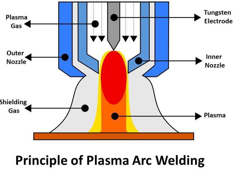
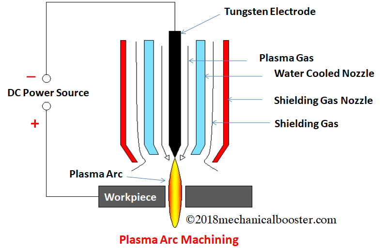
Plasma-arc machining (PAM) employs a high-velocity jet of high-temperature gas to melt and displace material in its path called PAM, this is a method of cutting metal with a plasma-arc, or tungsten inert-gas-arc, torch. The torch produces a high velocity jet of high- temperature ionized gas called plasma that cuts by melting and removing material from the work piece. Temperatures in the plasma zone range from 20,000° to 50,000° F (11,000° to 28,000° C). It is used as an alternative to oxyfuel-gas cutting, employing an electric arc at very high temperatures to melt and vaporize the metal. Equipment: A plasma arc cutting torch has four components: 1. The electrode carries the negative charge from the power supply. 2. The swirl ring spins the plasma gas to create a swirling flow pattern. 3. The nozzle constricts the gas flow and increases the arc energy density. 4. The shield channels the flow of shielding gas and protects the nozzle from metal spatter. Principle of operation: PAM is a thermal cutting process that uses a constricted jet of high -temperature plasma gas to melt and separate metal. The plasma arc is formed between a negatively charged electrode inside the torch and a positively charged work piece. Heat from the transferred arc rapidly melts  the  metal,  and  the  high-velocity gas  jet  expels  the  molten  material  from  the  cut. Applications: The materials cut by PAM are generally those that are difficult to cut by any other means, such as stainless steels and aluminum alloys. It has an accuracy of about 0.008″.

Read More

PLASMA ARC WELDING (PAW)

Plasma arc welding (PAW) is a process of joining of metals, produced by heating with a constricted arc between an electrode and the work piece (transfer arc) or the electrode and the constricting nozzle (non transfer arc). Shielding is obtained from the hot ionized gas issuing from the orifice, which may be supplemented by an auxiliary source of shielding gas. Transferred arc process produces plasma jet of high energy density and may be used for high speed welding and cutting of Ceramics, steels, Aluminum alloys, Copper alloys, Titanium alloys, Nickel alloys. Non-transferred arc process produces plasma of relatively low energy density. It is used for welding of various metals and for plasma spraying (coating). Equipment: (1) Power source. A constant current drooping characteristic power source supplying the dc Welding current is required. It should have an open circuit voltage of 80 volts and have a duty cycle of 60 percent. (2) Welding torch. The welding torch for plasma arc welding is similar in appearance to a gas tungsten arc torch but it is more complex. (a) All plasma torches are water cooled, even the lowest-current range torch. This is because the arc is contained inside a chamber in the torch where it generates considerable heat. During the non-transferred period, the arc will be struck between the nozzle or tip with the orifice and the tungsten electrode. (b) The torch utilizes the 2 percent thoriated tungsten electrode similar to that used for gas tungsten welding. (3) Control console. A control console is required for plasma arc welding. The plasma arc torches are designed to connect to the control console rather than the power source. The console includes a power source for the pilot arc, delay timing systems for transferring from the pilot arc to the transferred arc, and water and gas valves and separate flow meters for the plasma gas and the shielding gas. The console is usually connected to the powe r source. The high-frequency generator is used to initiate the pilot arc. Principles of Operation: The plasma arc welding process is normally compared to the gas tungsten arc process. But in the TIG-process, the arc is burning free and unhandled, whereas in the plasma-arc system, the arc is necked by an additional water-cooled plasma-nozzle. A plasma gas – almost always 100 % argon –flows between the tungsten electrode and the plasma nozzle. The welding process involves heating a gas called plasma to an extremely high temperature and then ionizing it such that it becomes electrically conductive. The plasma is used to transfer an electric arc called pilot arc to a work piece which burns between the tungsten electrode and the plasma nozzle. By forcing the plasma gas and arc through a constricted orifice the metal, which is to be welded is melted by the extreme heat of the arc. The weld pool is protected by the shielding gas, flowing between the outer shielding gas nozzle and the plasma nozzle. As shielding gas pure argon-rich gas-mixtures with hydrogen or helium are used. The high temperature of the plasma or constricted arc and the high velocity plasma jet provide an increased heat transfer rate over gas tungsten arc welding when using the same current. This results in faster welding speeds and deeper weld penetration. This method of…

Read More

ELECTRON BEAM MACHINING (EBM)

As has already been mentioned in EBM the gun is operated in pulse mode. This is achieved by appropriately biasing the biased grid located just after the cathode. Switching pulses are given to the bias grid so as to achieve pulse duration of as low as 50 μs to as long as 15 ms. Beamcurrent is directly related to the number of electrons emitted by the cathode or available in the beam. Beam current once again can be as low as 200 μamp to 1 amp. Increasing the beam current directly increases the energy per pulse. Similarly increase in pulse duration also enhances energy per pulse. High-energy pulses (in excess of 100 J/pulse) can machine larger holes on thicker plates. The energy density and power density isgoverned by energy per pulse duration and spot size. Spot size, on the other hand is controlled by the degree of focusing achieved by the electromagnetic lenses. A higher energy density, i.e., for a lower spot size, the material removal would be faster though the size of the holewould be smaller. The plane of focusing would be on the surface of the work piece or just below the surface of the work piece. 1. Electrons generated in a vacuum chamber 2. Similar to cathode ray tube 3. Electron gun 4. Cathode – tungsten filament at 2500 – 3000 degC 5. Emission current – between 25 and 100mA (a measure of electron beam density) MRR: In the region where the beam of electrons meets the workpiece,…

Read More

THERMAL ENERGY BASED PROCESSES

 Laser–Beam Machining (LBM)     Electron Beam Machining   (EBM)     Plasma Arc Machining (PAM) Laser–Beam Machining Laser-beam machining is a thermal material-removal process that utilizes a high-energy, Coherent light beam to melt and vaporize particles on the surface of metallic and non-metallic work pieces. Lasers can be used to cut, drill, weld and mark. LBM is particularly suitable for making accurately placed holes. A schematic of laser beam machining is shown in Figure Different types of lasers are available for manufacturing operations which are as follows: •    CO2 (pulsed or continuous wave): It is a gas laser that emits light in the infrared region. It can provide up to 25 kW in continuous-wave mode. •    Nd:YAG: Neodymium-doped Yttrium-Aluminum-Garnet (Y3Al5O12) laser is a solid- state laser which can deliver light through a fiber-optic cable. It can provide up to 50 kW power in pulsed mode and 1 kW in continuous-wave mode. Figure: Laser beam machining schematic Applications LBM can make very accurate holes as small as 0.005 mm in refractory metals ceramics, and composite material without warping the work pieces. This process is used widely for drilling Laser beam cutting (drilling) •    In drilling, energy transferred (e.g., via Nd YAG laser) into the workpiece melts the material at the point of contact, which subsequently changes into a plasma and leaves the region. •    A gas jet…

Read More

ELECTROCHEMICAL GRINDING (ECG)

Electrochemical Grinding, or ECG, is a variation of ECM (Electrochemical Machining) that combines electrolytic activity with the physical removal of material by means of charged grinding wheels. Electrochemical Grinding (ECG) can produce burr free and stress free p arts without heat or other metallurgical damage caused by mechanical grinding, eliminating the need for secondary machining operations. Like ECM, Electrochemical Grinding (ECG) generates little or no heat that can distort delicate components. Electrochemical Grinding (ECG) can process any conductive material that is electrochemically reactive. The most common reason customers choose Electrochemical Grinding (ECG) is for the burr free quality of the cut. If a part is difficult or costly to deburr, then ElectrochemicalGRINDING (ECG) is the best option. Materials that are difficult to machine by conventional methods, that work harden easily or are subject to heat damage are also good candidates for the stress free and no heat characteristics of Electrochemical Grinding (ECG). The stress free cuttingcapability of the process also makes it ideal for thin wall and delicate parts. The real value of Electrochemical Grinding (ECG) is in metalworking applications that are too difficult or time-consuming for traditional mechanical methods (milling, turning, grinding, deburring etc.). It is also effective when compared to non-traditional machining processes such as wireand sinker EDM. Electrochemical Grinding (ECG) is almost always more cost effective than EDM. Electrochemical Grinding (ECG) differ from conventional grinding Conventional surface grinding typically uses shallow reciprocating cuts that sweep across the work surface to create a flat plane or groove. Another conventional surface grinding process, creep feed grinding, typicallyuses slower feeds than conventional surface grinding and removes material in deep cuts. Because of the abrasive nature of these processes, the equipment used must be rigid and this is especially true of creep feed grinding. Quality Electrochemical Grinding (ECG) machines must also be rigid for close tolerance results but since very little of the material removed is done so abrasively the machines do not have to be as massive as their conventional counterparts. To a user familiar with creep feed grinding Electrochemical Grinding (ECG) will appear to be very similar, that is, relatively slow feeds (as compared to conventional surface grinding) and deep cuts as opposed to shallow reciprocating cuts. Electrochemical Grinding (ECG) is a combination of electrochemical (Anodic)dissolution of a  material, according to Faraday’s Law, and light abrasive action. The metal is decomposed to some degree by the DC current flow between the conductive grinding wheel (Cathode) and the work piece (Anode) in the presence of an electrolyte solution. Unlike conventional grinding techniques, Electrochemical Grinding (ECG) offers the ability to  machine  difficult  materials  independent  of  their  hardness  or  strength.  Electrochemical Grinding (ECG) does not rely solely on an abrasive process; the results are precise burr free and stress free cuts with no heat and mechanical distortions. Electrochemical Grinding (ECG) compare to EDM, laser, water-jet and other non-traditional technologies EDM and laser both cut metal by vaporizing the material at very high temperatures. This results in a re-cast layer and a heat affected zone on the material surface. Electrochemical Grinding (ECG) is a  no heat process that never causes metallurgical damage. Electrochemical Grinding (ECG) is usually much faster than EDM but typically is less accurate. Laser cutting can be very fast and accurate but it is normally limited to thin materials. Water -jet cutting can be quite fast and usually leaves no metallurgical damage but the consumable costs can be very high and the cuts are limited to jigsaw type cuts much like Wire EDM. In most cases, ElectrochemicalGrinding (ECG) is a more accurate process than water-jet. Another difference between water jet and laser machining compared to electrochemical grinding (ecg) is laser and water jet can both process materials that are not conductive. edm and electrochemical grinding (ecg) processes canonly work on materials that are conductive. Tolerances can be achieved with electrochemical grinding (ecg) the tolerances that can be achieved using electrochemical grinding (ecg) depend greatly on the material being cut, the size and depth of cut and ecg parameters being used. On small cuts, tolerances of .0002” (.005mm) can be achieved with careful control of the grinding parameters. Surface Finishes Can Be Achieved With Electrochemical Grinding (Ecg) The Electrochemical Grinding (ECG) process does not leave the typical shiny finish of abrasive grinding. This is because there is no smearing of the metal as in conventional grinding. A 16 micro inch finish or better can be achieved but it will have a matte (dull) rather than a polished look. Materials Can Be Cut With Electrochemical Grinding (ECG) Almost any conductive metal can cut with Electrochemical Grinding (ECG). Steel, Aluminum, Copper, Stainless Steels, Inconel and Hastelloy cut very freely with Electrochemical Grinding (ECG). Nickel/Titanium, Cobalt alloys, Amorphous metals, Berilium, Berilium Copper, IridiumNeodymium Iron Boron, Titanium, Nickel/Titanium, Nitinol, Powdered Metals, Rene 41, Rhenium, Rhodium, Stelllite, Vitalium, Zirconium and Tungsten can also be cut effectively….

Read More

ELECTROCHEMICAL HONING

Electrochemical honing is one of the non-equilibrium gap processes in ECM and is a new technique, which in spite of being used in some industrial plants especially to smooth surfaces, is still not fully described due to the variety of the factors affecting the process. More information about the process  is  required  especially the  effects  of  the  working  parameters  on  the  produced  surface roughness. A special honing tool was designed by using different tool tip shapes (rectangular, circular, triangle & inclined) to study the ability for improving the surface roughness. This work presents a study for the factors affecting the electrochemical honing process especially the machining time, work piece material, initial working gap, tool rotational speed, tool tip shape and the inclined tool tip angle. The results are finally furnished with the aim to generalize a useful guideline for the user to enable proper selection of conditions for obtaining good surface quality.

Read More

Electrochemical Machining (ECM)

Introduction Electrochemical machining (ECM)is a  metal-removal process based  on  the  principle ofreverse electroplating. In this process, particles travel from the anodic material (workpiece) toward the cathodic material (machining tool). A current of electrolyte fluid d carries away thedepleted material before it has a chance to reach the machining tool. The cavity produced is the female mating image of the tool shape.  Figure: ECM process Similar to EDM, the work piece hardness is not a factor, making ECM suitable for machining difficult-to –machine materials. Difficult shapes can be made by this process on materials regardless of their hardness. A schematic representation of ECM process is shown in Figure. The ECM tool is positioned very close to the work piece and a low voltage, high amperage DC current is passed between the work piece and electrode. Some of the shapes made by ECM process is shown in Figure.  Figure: Parts made by ECM Advantages of ECM •   The components are not subject to either thermal or mechanical stress. •   No tool wears during ECM process. •   Fragile parts can be machined easily as there is no stress involved. •    ECM deburring can debur difficult to access areas of parts. •    High surface finish (up to 25 µm in) can be achieved by ECM process. •    Complex geometrical shapes in high-strength materials particularly in the aerospace industry for the mass production of turbine blades, jet-engine parts and nozzles can be machined repeatedly and accurately. •    Deep holes can be made by this process. Limitations of ECM •    ECM is not suitable to produce sharp square corners or flat bottoms because of the tendency for the electrolyte to erode away sharp profiles. •    ECM can be applied to most metals but, due to the high equipment costs, is usually used primarily for highly specialized applications. Material removal rate, MRR, in ECM MRR = C .I. h     (cm3/min) C: specific (material) removal rate (e.g., 0.2052 cm3/amp-min for nickel); I:current (amp); h: current efficiency (90–100%). The rates at which metal can electrochemically remove are in proportion to the current passed through the electrolyte and the elapsed time for that operation. Many factors other than Current influence the rate of machining. These involve electrolyte type, rate of electrolyte flow, and someother process conditions.

Read More

Chemical milling

In chemical milling, shallow cavities are produced on plates, sheets, Forgings and extrusions. The two key materials used in chemical milling process are etchant and maskant. Etchants are acid or alkaline solutions maintained within controlled ranges of chemical composition and temperature. Maskants are specially designed elastomeric products that arehand strippable and chemically resistant to the harsh etchants. Steps in chemical milling •   Residual stress relieving: If the part to be machined has residual stresses from the previous processing, these stresses first should be relieved in order to prevent warping after chemical milling. •    Preparing: The surfaces are degreased and cleaned thoroughly to ensure both good adhesion of the masking material and the uniform material removal. •    Masking: Masking material is applied (coating or protecting areas not to be etched). •    Etching: The exposed surfaces are machined chemically with etchants. •    Damasking: After machining, the parts should be washed thoroughly to prevent further reactions with or exposure to any etchant residues. Then the rest of the masking material is removed and the part is cleaned and inspected. Applications: Chemical milling is used in the aerospace industry to remove shallow layers of material from large aircraft components missile skin panels (Figure 7), extruded parts for airframes. Figure: Missile skin-panel section contoured by chemical milling to improve the stiffness- to- weight ratio of the part

Read More

CHEMICAL AND ELECTRO CHEMICAL ENERGY BASED PROCESSES

Chemical Machining     Chemical milling     Electrochemical Machining     Electrochemical Honing     Electrochemical Grinding CHEMICAL MACHINING Chemical machining (CM) is the controlled dissolution of work piece material (etching) by means of a strong chemical reagent (etchant). In CM material is removed from selected areas of work piece by immersing it in a chemical reagents or etchants; such as acids and alkaline solutions. Material is removed by microscopic electrochemical cell action, as occurs in corrosion or chemical dissolution of a metal. This controlled chemical dissolution will simultaneously etch all exposed surfaces even though the  penetration rates  of  the  material  removal may be  only 0.0025 –0.1 mm/min. The basic process takes many forms: chemical milling of pockets, contours, overall metal removal, chemical blanking for etching through thin sheets; photochemical machining (pcm) for etching  by  using  of  photosensitive  resists  in  microelectronics;  chemical  or  electrochemical polishing where weak chemical reagents are used (sometimes with remote electric assist) for polishing or deburring and chemical jet machining where a single chemically active jet is used. A schematic of chemical machining process is shown in Figure. Figure. (a) Schematic of chemical machining process (b) Stages in producing a profiled cavity by chemical machining

Read More

WIRE CUT ELECTRICAL DISCHARGE MACHINING (WCEDM)

EDM,  primarily,  exists  commercially in  the  form  of  die-sinking  machines  and  wire- process, a slowly moving wire travels along a prescribed path and removes material from the workpiece. Wire EDM uses electro-thermal mechanisms to cut electrically conductive materials. Thematerial is removed by a series of discrete discharges between the wire electrode and the workpiece in the presence of dielectric fluid, which creates a path for each discharge as the fluid becomes ionized in the gap. The area where discharge takes place is heated to extremely high temperature, so that the surface is melted and removed. The removed particles are flushed away by the flowing dielectric fluids. The wire EDM process can cut intricate components for the electric and aerospace industries. This non-traditional machining process is widely used to pattern tool steel for die manufacturing cutting machines (Wire EDM). The concept of wire EDM is shown in this Figure. Figure: Wire erosion of an extrusion die The wires for wire EDM is made of brass, copper, tungsten, molybdenum. Zinc or brass coated wires are also used extensively in this process. The wire used in this process should posse’s high tensile strength and good electrical conductivity. Wire EDM can also employ to cut cylindrical objects with high precision. The sparked eroded extrusion dies are presented in Figure. Figure: Sparked eroded extrusion dies This process is usually used in conjunction with CNC and will only work when a part is to Be cut completely through.  The melting temperature of the parts  to  bemachined is  an Important parameter for this process rather than strength or hardness. The surface quality and MRR of the machined surface by wire EDM will depend on different machining parameters such as applied peak current, and wire materials. The wires for wire EDM is made of brass, copper, tungsten, molybdenum. Zinc or brass coated wires are also used extensively in this process. The wire used in this process should posses’ high tensile strength and good electrical conductivity. Wire EDM can also employ to cut cylindrical objectswith high precision. The sparked eroded extrusion dies are presented in Figure 5. Figure: Sparked eroded extrusion dies This process is usually used in conjunction with CNC and will only work when a part is to Be cut  completely through.  The melting temperature of the  parts  to  be machined is  an important parameter for this process rather than strength or hardness. The surface quality and MRR of the machined surface by wire EDM will depend on different machining parameters such as applied peak current, and wire materials.

Read More