
A bicycle chain usually announces trouble before it stops doing its job. It becomes noisy, develops slack, shifts poorly, and eventually may skip under load. A brittle glass fuse, by contrast, can appear perfectly normal until one overload makes it open in an instant.
Machines behave the same way. Some components slowly lose material, clearance, stiffness, or accuracy. Others remain serviceable for a long time and then fracture, buckle, seize, or overload with little visible warning.
That difference matters to anyone who designs, operates, repairs, or inspects mechanical equipment. The maintenance strategy for a wearing bearing is not the strategy for a bolt that may fail from fatigue, and neither is appropriate for a pressure vessel approaching an unstable crack condition.
Understanding the failure mechanism changes the questions worth asking: What is changing over time? Is the damage visible? Does a small defect grow steadily, or can it cross a threshold and become catastrophic? Those questions turn “unexpected” failures into problems that can often be anticipated and managed.
🔍 Failure Is a Process, Not Just an Event
A mechanical failure is often described as a single moment: the shaft broke, the seal leaked, or the gear stripped. In engineering terms, that moment is usually the final result of a process involving load, material response, environment, geometry, and time.
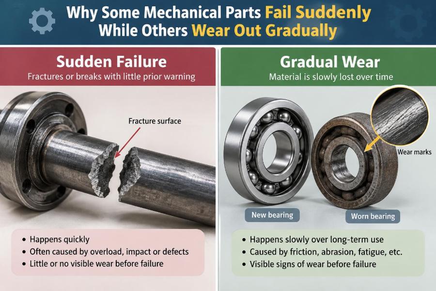
Gradual wear-out failure occurs when useful capability declines progressively. A sliding surface loses material, a bearing clearance increases, or a spring relaxes until the part no longer meets its required function.
Sudden failure occurs when a part crosses a critical limit. The trigger may be overload, crack growth, loss of stability, a manufacturing defect, or an unfavorable combination of smaller effects. The final event can be rapid even when the underlying damage developed over months.
🧭 Function Defines What “Failed” Means
A part need not split in two to fail. A pump shaft seal has failed when leakage exceeds what the system can tolerate. A precision guide has failed when wear causes positioning error, even if it still moves smoothly.
Conversely, a structural bracket may retain its shape until a crack reaches a critical size, then fail suddenly under a load that previously seemed ordinary. Engineers therefore define failure relative to function: strength, stiffness, sealing, alignment, efficiency, safety, or dimensional accuracy.
📉 The Typical Shape of Gradual Wear
Many wearing systems follow a recognizable pattern. There may be a short run-in period while microscopic high spots conform, followed by relatively stable service, then accelerated degradation as clearance, temperature, vibration, or contamination rises.
The key feature is that a measurable condition changes with use. Thickness falls, vibration trends upward, particles appear in lubricant, or power consumption increases. These trends create opportunities for inspection and planned replacement.
⚡ Why a Sudden Break Can Look Random
Sudden does not necessarily mean random. A component can have a hidden crack, internal void, sharp machining mark, or unfavorable residual stress for a long period. It may finally fail when normal service loading combines with one additional factor such as a cold temperature, misalignment, or a brief overload.
To an observer, the last load appears to be the cause. More accurately, it is often the final trigger in a chain of accumulated damage and reduced remaining strength.
🧱 Strength, Stress, and the Safety Margin
Stress is the internal force intensity produced when a load acts on a part. Strength is the stress level a material or component can withstand under specified conditions. A component works safely while its actual stresses remain below its usable strength with an appropriate margin.
Wear can increase stress by thinning a section or creating looseness. Damage can reduce strength by introducing a crack. Either direction closes the margin until normal operation is no longer safe.
A useful mental model is simple: failure becomes likely when the load effect becomes greater than the part’s remaining resistance.
🪨 Ductile Materials Often Give Warning
Ductile materials, such as many properly selected steels and aluminum alloys, can plastically deform before fracture. Plastic deformation means the material changes shape permanently instead of returning fully to its original form after unloading.
A bent bracket, stretched bolt, or dented guard can therefore provide a visible warning that a load limit has been exceeded. This is valuable, but it is not a guarantee of safe behavior: a ductile material can still fracture suddenly under fatigue, low temperature, high loading rate, or severe stress concentration.
🧊 Brittle Behavior Leaves Less Room for Error
Brittle fracture involves little plastic deformation before a crack propagates. Cast iron, ceramics, hardened materials, and some steels in unfavorable temperature or constraint conditions can behave this way.
Because there may be little bending or distortion beforehand, brittle failure can seem abrupt. A small notch, impact mark, or crack can have a larger effect than its appearance suggests, particularly where tensile stress is high.
🧬 Microstructure Influences the Failure Path
Metals are not perfectly uniform blocks. Their grains, phases, inclusions, heat-treatment condition, and prior processing affect hardness, toughness, fatigue resistance, and corrosion behavior. Polymers and composites have their own internal structures, fiber directions, interfaces, and aging mechanisms.
Two parts with the same shape and nominal material label may not perform identically if heat treatment, molding, welding, or surface finishing differs. This is why material specifications and process control matter as much as the drawing’s dimensions.
📐 Stress Concentrations Start Many Problems
A hole, keyway, thread root, sharp inside corner, scratch, or sudden change in section interrupts the smooth flow of force through a component. Stress becomes locally higher than the average calculated from load divided by area. This local amplification is called a stress concentration.
Rounded transitions, good surface finish, proper thread engagement, and avoiding unnecessary notches can substantially improve durability. A part does not usually fail at its largest, strongest-looking region; it often fails at the smallest geometric detail carrying the highest local stress.
🔁 Fatigue: Damage From Repeated Loading
Fatigue is one of the most misunderstood reasons parts fail suddenly. It occurs when repeated stress cycles initiate and grow cracks, sometimes at stress levels below the material’s one-time static strength.
A rotating shaft experiences alternating bending: the same surface point moves from tension to compression every revolution. A vehicle suspension component experiences cycles from road loads. A bolted joint can experience cyclic load changes from vibration or pressure fluctuations.
The final fracture may be quick, but fatigue usually has stages: crack initiation, stable crack growth over many cycles, and final overload when too little intact material remains.
🔬 Fracture Surfaces Can Tell a Story
Failure analysis often begins with preserving and examining the broken surfaces. On a fatigue fracture, one region may appear smoother from slow crack growth, while the final overload region is rougher. The origin may be near a notch, corrosion pit, or surface defect.
Interpretation requires care. Handling a broken part can damage evidence, and visual appearance alone is not always conclusive. Still, fracture features, deformation, corrosion products, wear patterns, and component history together can reveal far more than the phrase “it just broke.”
🛢️ Wear Is More Than Parts Rubbing Together
Wear is material loss or surface damage caused by contact and relative motion. It is not always undesirable; controlled wear can occur during running-in. Trouble begins when wear changes fit, creates debris, raises friction, or exposes weaker layers.
Common forms include adhesive wear, where microscopic junctions tear material away; abrasive wear, where hard particles or rough asperities cut surfaces; and fretting wear, where tiny oscillatory movements damage a contact interface.
🧪 Lubrication Separates Surfaces and Controls Heat
A lubricant can form a film that separates moving surfaces, reducing direct metal-to-metal contact. It also carries heat and debris away from loaded zones. Whether a full fluid film exists depends on speed, load, viscosity, geometry, and temperature.
Too little lubricant is an obvious risk, but the wrong lubricant can also cause failure. A viscosity that is unsuitable at operating temperature, incompatible additives, water contamination, or blocked supply passages can move a machine from low-friction operation to rapid scuffing or seizure.
🌪️ Contamination Accelerates Otherwise Normal Wear
Dirt, metal particles, water, and process chemicals can turn a healthy contact into an abrasive or corrosive one. A hard particle passing through a bearing or hydraulic valve may score surfaces and create additional debris, producing a damaging feedback loop.
Good sealing and filtration are not minor housekeeping details. They preserve the surface condition on which bearing life, gear contact quality, and hydraulic precision depend.
🌡️ Temperature Changes Both Loads and Materials
Temperature affects dimensions, lubrication, stiffness, strength, and corrosion rate. If two joined materials expand by different amounts, thermal cycling can create stresses even when no external force changes.
High temperature can soften some materials, degrade polymer seals, reduce lubricant viscosity, and promote oxidation. Low temperature can reduce toughness in certain materials. Design must consider the actual operating range, including start-up, shutdown, and local hot spots—not only the average temperature.
🧂 Corrosion Can Cause Gradual Loss or Sudden Fracture
Uniform corrosion gradually reduces thickness and is often visible. Localized corrosion, such as pitting or crevice corrosion, is more deceptive because it creates deep local defects while much of the surface may look acceptable.
A corrosion pit is also a stress concentrator. Under cyclic loading, it can become a fatigue crack origin. Some material-environment combinations can develop cracking mechanisms that are difficult to detect without targeted inspection, so material selection and environmental control must be considered together.
🪢 Fasteners Fail When Joint Behavior Is Misunderstood
Bolts are often blamed when joints loosen or fracture, but the root cause may be poor preload, joint separation, uneven contact, vibration, wrong tightening method, or an inadequate clamping arrangement. Preload is the intentional tension created during tightening; it helps keep joint members compressed.
If an external cyclic load repeatedly unloads the bolt, fatigue risk rises sharply. A bolt that is merely made “stronger” may not solve the underlying joint-design problem. Correct grip length, seating surfaces, torque or tension control, and resistance to loosening all matter.
⚙️ Gears Show Both Wear and Sudden Failure Modes
Gear teeth may gradually wear, polish, pit, or score as lubrication and alignment conditions deteriorate. Those changes can increase backlash, noise, and vibration before function is lost.
But a gear tooth can also break suddenly from bending fatigue at its root, an impact load, a manufacturing defect, or severe overload. The same gearbox may therefore require both trend monitoring for wear and periodic inspection for crack-prone regions.
🧷 Bearings Often Offer Early Clues
Rolling-element bearings commonly develop surface fatigue, contamination damage, inadequate-lubrication distress, or cage problems. Increasing vibration, temperature, noise, and lubricant debris can provide useful warning, though the signals are not unique to one failure mechanism.
A bearing can transition from a minor defect to rapid damage when spalling debris circulates through the contact zone. Monitoring helps, but interpretation should consider load, speed, mounting condition, and lubrication history rather than relying on one measurement alone.
📏 Misalignment Creates Loads the Drawing Did Not Show
Two shafts can be individually straight and still be misaligned when coupled. Misalignment introduces cyclic bending, edge loading, seal wear, coupling stress, and additional bearing load. Soft foundations, thermal movement, pipe strain, and worn mounts can all shift alignment after installation.
Because the effects accumulate gradually, misalignment may first appear as heat, vibration, or recurring seal and bearing replacements. Replacing the damaged part without correcting the alignment simply restarts the failure cycle.
🌀 Buckling Is a Sudden Loss of Stability
Not all abrupt failures are fractures. A slender member under compression can buckle sideways once its critical load is reached. The material may still be below its compressive strength, yet the component loses its stable shape and its ability to carry load effectively.
Columns, thin panels, pipe sections, and sheet-metal structures are susceptible when unsupported length, geometry, imperfections, or load eccentricity are unfavorable. Buckling shows why strength alone is not enough; stiffness and stability must also be designed.
💥 Overload Failure Can Be a Design or Operating Issue
A one-time overload may come from impact, a jammed mechanism, improper lifting, pressure surge, collision, or an operator applying force beyond the intended limit. The part may yield, shear, or fracture depending on its material and geometry.
However, a component that fails during an overload is not automatically poorly designed. Designers may deliberately choose a sacrificial element, such as a shear pin, to protect a more expensive system. The important question is whether the failure occurred in the intended place and at an appropriate load.
🧩 Defects and Variability Reduce Predictability
Porosity in castings, lack of fusion in welds, machining damage, improper heat treatment, and assembly errors can reduce a part’s effective capability. Defects matter most when they lie in highly stressed regions or create crack-like geometry.
Quality control lowers risk but does not make every internal feature visible or every operating condition identical. Engineering accommodates this uncertainty through conservative design margins, inspection plans, traceability where justified, and process controls matched to the consequence of failure.
📊 Comparing Progressive and Threshold Failures
| Feature | Gradual wear-out behavior | Sudden or threshold behavior |
|---|---|---|
| Typical change | Material loss, clearance growth, efficiency decline | Crack propagation, overload, buckling, rupture |
| Visible warning | Often present, but may be subtle | May be limited or hidden |
| Useful monitoring | Thickness, vibration trend, temperature, debris, leakage | Crack inspection, load history, deformation, nondestructive testing |
| Maintenance approach | Condition-based or scheduled replacement | Design verification, targeted inspection, protection from overload |
| Common trap | Ignoring a worsening trend | Assuming normal appearance means no risk |
The categories overlap. For example, a fatigue crack grows gradually but can produce a sudden final break. Good maintenance programs identify the relevant damage process rather than forcing every issue into one category.
📈 Condition Monitoring Works Best With a Failure Model
Measuring vibration, temperature, oil condition, current draw, or acoustic signals can reveal change, but no instrument independently explains every cause. A rising bearing temperature could reflect lubrication trouble, increased load, misalignment, or restricted cooling.
Monitoring becomes powerful when paired with baseline data and an understanding of what changes should occur for a particular failure mode. The goal is not simply collecting numbers; it is detecting a meaningful departure from healthy operation.
🩺 Inspection Methods Must Match the Damage
Visual inspection can find corrosion, leakage, loose fasteners, rubbing, and deformation. Dye penetrant methods can reveal surface-breaking cracks in suitable nonporous materials. Magnetic particle inspection can detect certain near-surface discontinuities in ferromagnetic materials, while ultrasonic methods can investigate some internal flaws.
Each method has limitations related to material, geometry, access, surface condition, flaw orientation, and technician skill. An inspection plan should focus on credible damage locations, not merely on tests that are convenient to perform.
🗓️ Time-Based Replacement Has Limits
Replacing a belt, seal, bearing, or filter after a set interval can be sensible when service conditions are predictable and the consequence of failure is significant. It is less effective when actual life varies widely with contamination, loading, installation quality, or duty cycle.
Changing parts too early wastes useful life and can introduce assembly errors. Changing them too late raises downtime and safety risk. The best interval is informed by operating history, failure consequences, inspection capability, and the part’s known degradation behavior.
🛠️ Design Choices Can Make Failure More Manageable
Durable design does not always mean making every part larger or harder. It may mean adding a generous radius, improving drainage, relocating a weld away from peak stress, specifying a tougher material, using a replaceable wear liner, or providing access for lubrication and inspection.
Designers also consider fail-safe behavior: if a component does fail, can the system move to a safer condition rather than creating uncontrolled motion, release, or collapse? The appropriate choice depends on the application and the consequences involved.
🚫 Common Responses That Miss the Real Cause
- Replacing the same component repeatedly: This may treat the symptom while leaving misalignment, contamination, vibration, or overload unchanged.
- Choosing the hardest available material: Higher hardness can improve wear resistance but may reduce toughness or create other manufacturing challenges.
- Increasing lubrication without diagnosis: More grease can damage some bearing arrangements or mask the source of overheating.
- Judging health only by appearance: Hidden fatigue cracks and internal damage may not be visible from the outside.
- Blaming the operator immediately: Operating conditions matter, but unclear procedures, poor guarding, weak design margins, and inadequate maintenance can also contribute.
🧠 A Practical Failure-Investigation Sequence
- Make the equipment safe and preserve failed components, lubricant samples, and relevant settings.
- Document the operating state: load, speed, temperature, recent changes, alarms, and maintenance actions.
- Identify the actual failure mode before deciding on the root cause.
- Inspect related parts and interfaces, including mounts, fasteners, lubrication paths, and alignment.
- Compare evidence with plausible mechanisms such as wear, fatigue, corrosion, overload, or instability.
- Correct the system condition that enabled the failure, then verify that the corrective action works.
This sequence avoids a common mistake: treating the visibly broken part as the entire problem.
🎯 The Core Principle: Manage Damage Before It Reaches a Limit
Parts wear out gradually when their dominant mechanism produces progressive, measurable degradation. They fail suddenly when a crack, load, temperature, instability, or defect crosses a critical threshold faster than the system can adapt.
The engineering task is to identify which mechanism is credible, preserve a margin between demand and resistance, and use the right mix of design, operation, monitoring, inspection, and replacement. Some failures can be forecast from trends; others demand preventive controls because their warning signs are faint or inaccessible.
The most reliable way to reduce mechanical failure is not to wait for a symptom, but to understand the damage process that creates it.
Whether a component becomes noisy over thousands of hours or breaks during one routine cycle, its behavior follows physical causes that can be investigated and managed. Better questions, careful evidence, and designs that respect real operating conditions make machinery more dependable—and failures far less mysterious. ⚙️ 🔍 🛠️