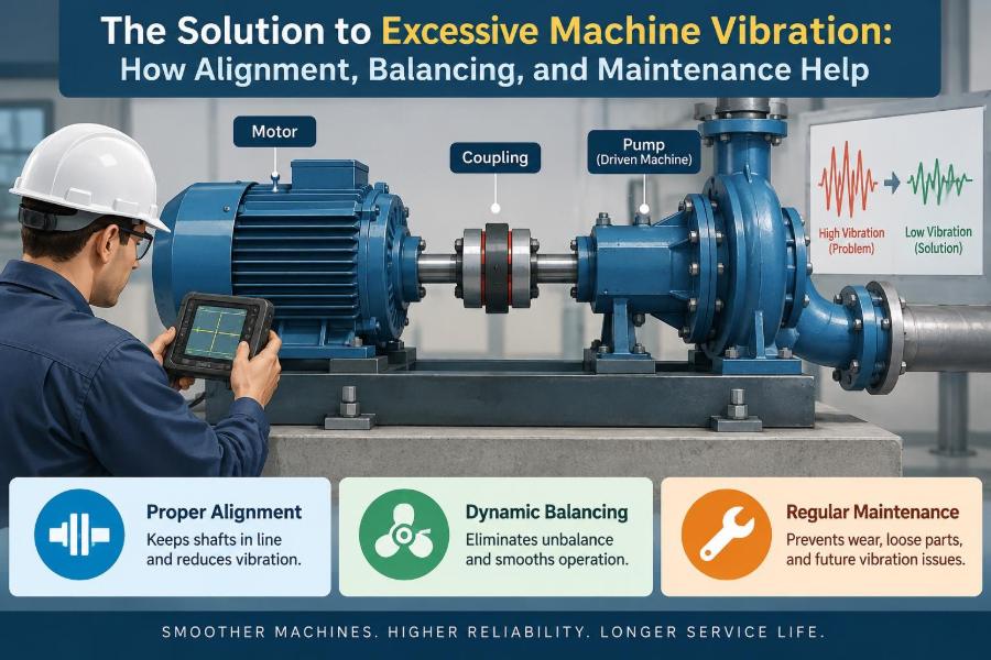

A pump begins to hum more loudly than usual. A fan casing feels rough to the touch. On a production line, a motor that once ran smoothly now shakes its mounting bolts loose. These are familiar moments in workshops, plants, and maintenance rooms—and they are rarely problems to ignore.
Some vibration is normal. Rotating equipment cannot operate with perfectly zero motion, and a machine’s structure will always respond slightly to changing loads. Trouble begins when the vibration level, frequency, or pattern changes in a way that points to a developing fault.
Excessive vibration wastes energy, shortens bearing and seal life, loosens fasteners, damages couplings, and can eventually stop a process without warning. It also makes diagnosis harder: one defect can create forces that conceal another.
The most effective response is not simply tightening bolts or replacing the noisiest part. It is a disciplined approach built around understanding the vibration, correcting alignment and balance, and maintaining the machine so the condition does not return.
🔎 What Excessive Machine Vibration Actually Means
Machine vibration is the repeated movement of a component around its normal position. In rotating machinery, this movement may be radial, axial, vertical, horizontal, or a combination of directions.
Excessive vibration means motion beyond what is acceptable for that machine, its speed, its foundation, and its duty. A value that is concerning on a precision spindle may be ordinary on a large, slow-moving structure, so the machine context matters.
Just as useful as the overall level is the trend. A steady increase from the machine’s own healthy baseline often deserves attention even when a single reading does not appear dramatic.
📈 Why Vibration Becomes a Reliability Problem
Vibration creates alternating forces. Those forces repeatedly load shafts, bearing races, mounting feet, pipe connections, electrical terminals, and structural welds.
Over time, cyclic loading can produce fatigue cracks or loosen joints. It can also disturb the thin lubricant film that separates rolling elements or journal-bearing surfaces, increasing friction and wear.
In process equipment, vibration may affect product quality as well. A vibrating mixer, conveyor, machine tool, or filling system can introduce inconsistency long before it reaches a point of mechanical failure.
🧭 Start by Defining Normal Operation
A useful vibration program begins with a baseline taken when equipment is known to be correctly installed and operating under representative load. Record speed, load, temperature, measurement location, sensor direction, and any unusual process conditions.
Without this reference, a technician may only be able to say that a machine is vibrating. With it, the question becomes more valuable: what changed, where, and at what rate?
Baseline data should not be treated as permanent. A major overhaul, new foundation, different impeller, or changed operating speed can establish a new normal condition.
🎵 Frequency Is the Clue Behind the Motion
Vibration amplitude describes how much a machine moves, but frequency describes how often that motion repeats. Frequency analysis helps connect a vibration pattern to a physical source.
For example, a rotor running at 1,500 revolutions per minute has a running frequency of 25 hertz, or 25 cycles per second. A strong vibration component at that rate is often called 1× running speed.
Higher multiples, such as 2× running speed, and non-integer frequencies can point toward different faults. Interpretation requires care because several defects can create overlapping patterns.
🧰 Choose Measurements That Answer the Question
Handheld meters are useful for screening overall vibration. Accelerometers, velocity sensors, and displacement probes provide different views of machine behavior.
- Acceleration is often useful for higher-frequency impacts, such as those associated with developing rolling-element bearing defects.
- Velocity is widely used to assess general machine vibration over common operating ranges.
- Displacement is especially relevant where shaft motion relative to a bearing is critical, such as certain fluid-film bearing machines.
The instrument does not diagnose the fault by itself. Good sensor placement, repeatable measurement direction, and awareness of machine speed are just as important as the device.
⚖️ Unbalance: When Mass Is Not Evenly Distributed
Unbalance occurs when a rotating part’s center of mass does not lie on its axis of rotation. As speed rises, the resulting centrifugal force rises sharply, which explains why a small mass error can become serious at high rotational speed.
A ceiling fan with dust concentrated on one blade gives a simple analogy. Industrial examples include fans with buildup on blades, pump impellers with erosion, grinding wheels, rotors, and motor armatures.
Unbalance commonly produces prominent vibration near 1× running speed, often strongest in radial directions. That pattern is a clue, not a verdict; looseness and misalignment can also produce significant 1× vibration.
🌀 Static and Couple Unbalance Are Different Faults
Static unbalance exists when one heavy point causes a rotor to settle in the same orientation when supported freely. Adding or removing mass in one correction plane may resolve it.
Couple unbalance occurs when mass errors at opposite ends of a rotor create a rocking couple. The rotor may appear balanced in one plane but still generate vibration when spinning.
Long rotors, wide impellers, and high-speed assemblies frequently need correction in two planes. Treating a two-plane problem as a one-plane problem can reduce vibration at one location while worsening it at another.
🏭 Field Balancing Restores a Rotor in Its Installed Condition
Field balancing uses measured vibration and phase information to determine where correction mass should be added or removed on an installed rotor. It accounts for the actual rotor, shaft, supports, and operating environment.
A trial weight is sometimes used to establish how the system responds. Software or calculation methods then estimate the final correction weight and angular location.
Balancing should only be performed after the machine is mechanically sound. A loose bearing housing, cracked support, bent shaft, or rubbing seal can make balance corrections misleading or unsafe.
📏 Shaft Alignment Connects Two Machines Correctly
Alignment concerns the relative position of rotating shafts connected by a coupling, such as a motor driving a pump, gearbox, compressor, or fan. The shafts do not need to be one continuous line, but their centerlines must meet the coupling manufacturer’s allowable limits.
When alignment is poor, the coupling must flex repeatedly as the shafts turn. That transmits unwanted loads into bearings, seals, and shafts.
A flexible coupling accommodates limited movement; it does not make inaccurate alignment harmless. Its flexibility is intended to handle small residual errors and operating movement, not to compensate for careless installation.
↔️ Offset and Angular Misalignment Create Different Loads
Offset, sometimes called parallel misalignment, means the shaft centerlines are parallel but separated. Angular misalignment means the centerlines meet at an angle rather than lying parallel.
Real installations often contain both. Their effects can include elevated axial vibration, bearing heat, coupling wear, seal leakage, and a spectrum with 1× and 2× components.
| Condition | Simple description | Likely mechanical consequence |
|---|---|---|
| Offset misalignment | Shaft centerlines are displaced | Radial loading and coupling flexing |
| Angular misalignment | Shafts meet at an angle | Alternating bending and axial forces |
| Combined misalignment | Both conditions occur together | Complex loading and faster component wear |
Vibration signatures alone cannot reliably separate every alignment condition. Measurement at the coupling remains the proper basis for correction.
🔦 Alignment Methods: Straightedges, Dials, and Lasers
A straightedge and feeler gauges can identify gross errors on simple equipment, but their accuracy is limited. Dial indicators provide more detail and are suitable when used with a sound procedure.
Laser alignment systems offer rapid, repeatable measurement and can guide horizontal and vertical corrections. They are especially helpful for documenting results and reducing calculation errors.
Technology does not replace preparation. Coupling runout, dirty mounting surfaces, loose bolts, incorrect shim use, and a distorted base can undermine even a sophisticated alignment system.
🌡️ Thermal Growth Can Undo a Cold Alignment
Machines change position as they warm. A driven pump and its motor may grow vertically at different rates because they have different temperatures, materials, and support arrangements.
If a machine is aligned perfectly while cold but operates much hotter, its shaft centerline may move outside the desired operating position. This is why some machines require intentional thermal growth targets during cold alignment.
Reliable targets come from manufacturer guidance, operating measurements, or carefully justified engineering estimates. Guessing can be worse than applying no thermal correction at all.
🦶 Soft Foot Distorts the Machine Before It Runs
Soft foot exists when one or more machine feet do not sit flat on the base. Tightening the hold-down bolts bends the machine frame, potentially changing shaft alignment and creating stress in the casing.
Common causes include uneven foundations, warped feet, paint buildup, debris, excessive shim stacks, and pipe strain. A machine may appear aligned until its bolts are tightened, then shift out of tolerance.
Check soft foot before final alignment. Correcting it may require cleaning contact surfaces, machining a damaged foot, improving the base, or using properly fitted shims.
🧱 A Rigid Foundation Is Part of the Machine
The foundation and support structure determine how vibration forces are transmitted and amplified. Loose anchor bolts, cracked grout, corroded baseplates, or flexible steelwork can make a moderate rotating force appear as severe machine vibration.
A foundation should provide stable support without introducing distortion. Pipe supports matter too: unsupported piping can impose forces on pump casings and shift alignment after startup.
Before blaming the rotor, inspect the path from machine feet to floor. A poor structural connection cannot be corrected permanently with balancing weights alone.
📢 Resonance Amplifies a Small Excitation
Every structure has natural frequencies at which it responds readily. Resonance occurs when a forcing frequency—often related to running speed, blade passage, or gear meshing—approaches one of those natural frequencies.
The result can be unusually high vibration even when the original forcing source is modest. A fan that runs smoothly at one speed but shakes severely during a narrow speed range is a common warning sign.
The fix may involve changing operating speed, increasing stiffness, altering mass, improving support conditions, or modifying the excitation source. Adding damping can help in some cases, but it should not be assumed to solve every resonance problem.
🪛 Mechanical Looseness Changes the Whole Response
Mechanical looseness includes loose hold-down bolts, worn bearing fits, clearance in a pedestal, damaged keys, or movement between parts that should act as one. It allows impacts and nonlinear motion rather than smooth elastic response.
Looseness often produces harmonics of running speed and may cause readings to vary noticeably between measurements. It can also accelerate other defects because parts strike or rub under load.
Inspection is essential. A spectrum can suggest looseness, but only physical checks can identify whether the movement is at the foot, bearing housing, coupling, baseplate, or another interface.
🛢️ Bearings Need the Right Lubrication, Not More Lubrication
Bearings are frequent victims of excessive vibration, but they are not always the original cause. Misalignment, imbalance, contamination, and poor fits can all damage bearings prematurely.
Lubrication errors create their own problems. Too little grease may leave surfaces inadequately protected, while too much can raise churning losses and temperature. The wrong lubricant viscosity or grease type can also prevent proper film formation.
Use the machine manufacturer’s lubrication guidance and a controlled schedule. Keep lubricant clean, use clean tools, and avoid treating every noisy bearing as a reason to add grease.
🧼 Contamination and Wear Produce Distinctive Symptoms
Dirt, water, corrosion products, and metal debris can damage rolling surfaces and lubricant films. As defects develop, impacts may create higher-frequency vibration that becomes clearer in enveloped or demodulated acceleration measurements.
However, bearing diagnosis is probabilistic rather than automatic. Load changes, electrical damage, poor mounting, and nearby impacts may create similar features.
Confirm a suspected bearing issue with operating temperature, lubrication condition, audible noise, inspection history, and—where appropriate—ultrasound or oil analysis. Replacing a bearing without removing the underlying cause often starts the same failure cycle again.
⚙️ Belts, Gears, and Pulleys Add Their Own Frequencies
Not every vibration problem comes from direct-coupled shafts. Belt-driven systems can develop belt-frequency vibration from incorrect tension, worn belts, misaligned sheaves, or pulley eccentricity.
Gearboxes introduce gear-mesh frequencies and sidebands related to shaft speeds. A damaged tooth, backlash issue, or poor lubrication may alter these patterns, but gear noise also depends heavily on load and casing response.
Document the complete power path. Knowing the number of gear teeth, pulley diameters, belt arrangement, and shaft speeds gives the analyst a map for separating likely sources.
⚡ Electrical Faults Can Look Mechanical
Motor vibration may be influenced by electrical imbalance, rotor bar problems, air-gap eccentricity, or electromagnetic forces. These faults can interact with mechanical resonance and make diagnosis more complicated.
Checking supply condition, current balance, motor temperature, and operating load can prevent a purely mechanical investigation from missing an electrical cause. Electrical tests should be performed by qualified personnel using appropriate safety procedures.
A motor that becomes smoother when disconnected from its driven equipment may still have an electrical issue, but it may also be reacting to load, alignment, or structural conditions. Isolate variables carefully.
🧪 Use a Step-by-Step Diagnostic Sequence
Random adjustments can turn a solvable problem into a confusing one. A structured sequence preserves evidence and avoids correcting a symptom before finding the mechanism.
- Verify the complaint: compare current readings, noise, and operating condition with baseline information.
- Inspect for obvious hazards: loose guards, leaking seals, hot bearings, rubbing, damaged mounts, and insecure fasteners.
- Record speed, load, process state, and measurement locations before changing anything.
- Check foundation integrity, soft foot, piping strain, and mechanical looseness.
- Measure and correct alignment, then assess balance if the rotor and supports are sound.
- Re-test under comparable conditions and document the result.
When the consequence of failure is high, involve a vibration specialist or the equipment manufacturer rather than relying on a single indicator.
📍 Measure in More Than One Direction
A single reading can miss the geometry of a problem. Measure near bearings in horizontal, vertical, and axial directions where access and machine design permit.
Radial readings are often informative for unbalance and structural response. Axial vibration can provide valuable evidence of misalignment, thrust issues, or certain coupling problems.
Consistency is crucial. Mark measurement points, use the same sensor mounting method, and collect data at comparable speed and load. Otherwise, apparent changes may come from the test method rather than the machine.
🧑🔧 Correct the Cause Before Replacing Components
Replacing a failed bearing, coupling insert, or seal may restore operation briefly, but it does not necessarily restore reliability. If the machine is misaligned or its base is loose, the new part inherits the same harmful conditions.
A better repair scope connects the failed component to its likely loading environment. For example, a repeated seal failure should prompt checks of alignment, shaft runout, bearing condition, process pressure, dry running, and piping forces.
This approach may take longer during the repair, yet it reduces the chance of repeated downtime and makes future maintenance more predictable.
🗓️ Preventive Maintenance Is Not Just a Calendar
Time-based tasks remain useful for lubrication, inspections, and safety checks, but vibration-related maintenance benefits from condition information. A machine operating lightly in a clean environment may age differently from an identical machine operating continuously under variable load.
Condition-based maintenance uses trends in vibration, temperature, lubrication, and performance to decide when intervention is justified. It does not eliminate scheduled work; it makes the schedule more informed.
Practical programs begin simply: identify critical machines, establish routes, collect repeatable data, and review changes. A complicated system that no one has time to use is less valuable than a modest program performed consistently.
🧾 Good Records Turn Repairs into Learning
Record alignment results, shim changes, balance corrections, bearing replacements, lubrication details, vibration plots, and operating observations. Include what was found during disassembly, not just what was replaced.
Over several maintenance cycles, records reveal repeat patterns: a fan that accumulates material, a pump affected by pipe strain, or a motor that shifts after thermal cycling. These observations guide permanent improvements.
Clear records also help handovers. The next technician should be able to see why a setting was chosen rather than reverse-engineering past work from scattered notes.
🚫 Common Fixes That Often Fail
Several tempting actions produce short-term quietness without solving the underlying issue:
- Adding balance weights before checking looseness, rotor damage, and buildup.
- Aligning shafts before correcting soft foot or releasing pipe strain.
- Over-greasing a bearing because its vibration has increased.
- Using a flexible coupling to excuse large alignment errors.
- Comparing readings taken at different loads, speeds, or locations as if they were identical tests.
- Changing several variables at once and losing the ability to tell what worked.
Each mistake has the same weakness: it treats vibration as an isolated number rather than a response of an entire mechanical system.
🦺 Safety Comes Before Diagnostic Curiosity
Vibration work often takes place near rotating shafts, hot surfaces, live electrical equipment, pressurized piping, and elevated structures. Guards, lockout procedures, safe access, and site-specific rules are not optional details.
Never touch a rotating machine to “feel” its condition, and do not make balance or alignment adjustments while equipment is energized unless a controlled procedure specifically requires operation and qualified personnel are performing it.
High vibration can indicate an unstable condition. If there is evidence of rubbing, structural movement, rapidly rising temperature, damaged guards, or a risk to people, stop and secure the equipment according to the applicable procedure.
🎯 A Practical Plan for Alignment, Balancing, and Maintenance
Reliable vibration control follows a simple principle: remove the forces that should not exist, then make sure the machine structure can carry the forces that remain.
In practice, that means establishing a baseline, inspecting the foundation and mounts, correcting soft foot and pipe strain, aligning shafts for operating conditions, balancing sound rotors, and maintaining bearings and lubrication with clean, repeatable practices.
There is no universal vibration number or single corrective tool that fits every machine. The lasting solution is to diagnose the system, correct the root cause in the right order, and verify the result with consistent measurements.
A smoother-running machine is rarely the result of one adjustment alone. It is the outcome of sound installation, accurate alignment, appropriate balance, careful lubrication, and maintenance decisions based on evidence rather than guesswork. ⚙️📈🛠️