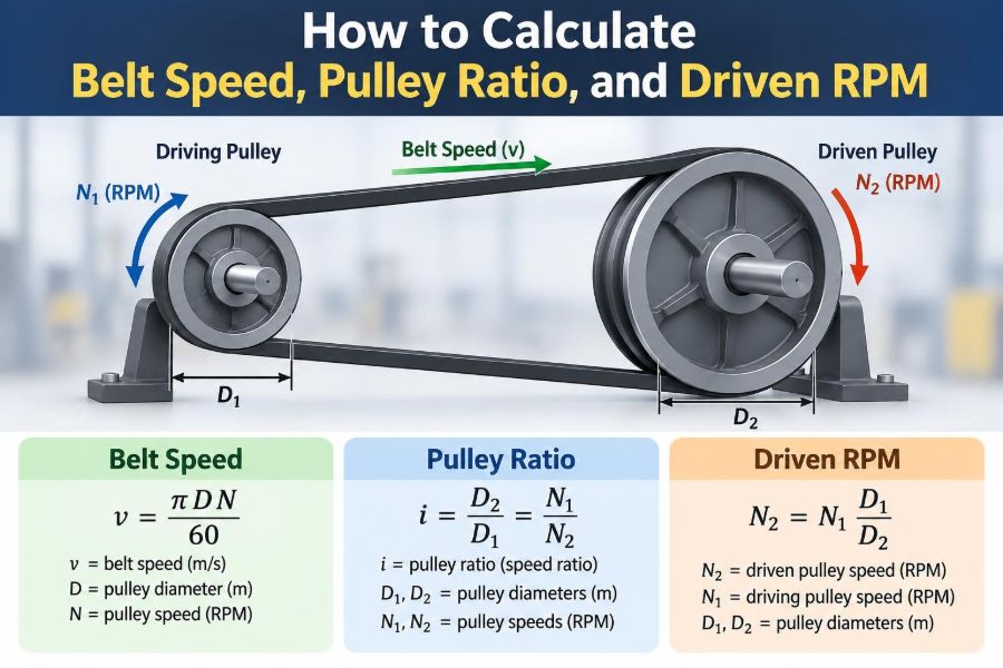

A belt drive can look deceptively simple: two pulleys, a flexible belt, and a motor. Yet a small error in pulley diameter or speed calculation can leave a conveyor moving too slowly, a fan producing too little airflow, or a pump running beyond its intended range.
Students often meet belt-drive equations as short formula exercises. Working professionals meet them during troubleshooting, retrofit work, machine selection, and maintenance—where the answer must account for real pulley sizes, slip, and safe operating limits.
The useful idea is that a belt transfers nearly the same linear speed around both pulleys. The pulley diameters then determine how that shared belt speed becomes rotational speed in revolutions per minute, or RPM.
Once that relationship is clear, belt speed, pulley ratio, and driven RPM become connected parts of one practical calculation rather than separate formulas to memorize.
⚙️ The Three Quantities You Need
Most belt-drive problems involve three related quantities: pulley rotational speed, pulley size, and belt linear speed. Rotational speed is commonly expressed in RPM. Pulley size is usually expressed as diameter, while belt speed is a distance per unit time, such as metres per second or feet per minute.
A fourth quantity, the pulley ratio, describes how the driver and driven pulley diameters compare. It predicts whether the driven shaft runs faster or slower than the motor shaft.
🔄 Driver and Driven Pulley Definitions
The driver pulley is attached to the power source, such as an electric motor, engine, or gearbox output shaft. The driven pulley receives motion and transmits it to the machine being powered.
Always label the pulleys before inserting numbers into a formula. A 100 mm pulley can be either driver or driven; its effect on speed depends entirely on which shaft it is mounted on.
📏 Why Pulley Diameter Controls Speed
One revolution of a pulley moves a length of belt equal to its circumference. For a pulley diameter D, circumference is πD. A larger pulley therefore carries more belt past a point in one revolution than a smaller one.
If both pulleys share the same belt speed, the smaller pulley must turn more times each minute to move the same belt length. This is the physical reason a small driven pulley increases shaft RPM.
🏃 What Belt Speed Actually Means
Belt speed is the tangential, or rim, speed at the pulley surface: the speed at which the belt travels around the drive. It is not the same thing as the shaft RPM.
For an ideal drive, belt speed is equal at the driver and driven pulleys. This common linear speed is the bridge between two shafts that may rotate at very different RPM values.
🧮 The Core Belt-Speed Formula
When diameter is in metres and rotational speed is in RPM, belt speed in metres per second is:
v = πDN / 60Here, v is belt speed in m/s, D is pulley pitch diameter in m, and N is pulley speed in RPM. The division by 60 converts revolutions per minute into revolutions per second.
With diameter in millimetres, use:
v = πDN / 60,000This version avoids converting millimetres to metres separately.
📐 Use Pitch Diameter, Not Just Outside Diameter
For V-belts, timing belts, and other profiled belts, the relevant diameter is usually the pitch diameter, sometimes called the effective diameter. It is the diameter at which the belt’s pitch line travels, not necessarily the outside edge of the pulley.
Using outside diameter may be close enough for a rough estimate, but it can introduce avoidable error in design or replacement work. Manufacturer catalogues provide pitch diameters and should take precedence over a tape-measure reading.
🔢 The Pulley-Ratio Formula
For an ideal open-belt or crossed-belt drive, the speed relationship is:
N₁D₁ = N₂D₂Subscript 1 refers to the driver and subscript 2 to the driven pulley. Rearranging for driven RPM gives:
N₂ = N₁ × D₁ / D₂This equation says that driven speed equals driver speed multiplied by driver diameter divided by driven diameter.
⬇️ Speed Reduction With a Larger Driven Pulley
Suppose a motor runs at 1,440 RPM with a 100 mm driver pulley. It drives a 200 mm driven pulley. The driven speed is:
N₂ = 1,440 × 100 / 200 = 720 RPMThe driven pulley is twice the diameter of the driver, so it turns at half the speed. This is a 2:1 speed reduction, often written as driver-to-driven speed reduction.
⬆️ Speed Increase With a Smaller Driven Pulley
Reverse the pulley sizes: a 200 mm driver turns a 100 mm driven pulley while the driver still runs at 1,440 RPM.
N₂ = 1,440 × 200 / 100 = 2,880 RPMThe driven shaft now turns twice as fast. Speed increase can be useful for a fan or centrifugal machine, but it must be checked against bearing, rotor, belt, and machine speed limits.
🧭 State Ratios Clearly to Avoid Confusion
The phrase “pulley ratio” can be ambiguous unless you state what is being compared. Diameter ratio and speed ratio are reciprocals.
| Comparison | For 100 mm driver and 200 mm driven | Meaning |
|---|---|---|
| Diameter ratio, driver:driven | 1:2 | Driven pulley is twice as large |
| Speed ratio, driver:driven | 2:1 | Driver turns twice as fast |
| Reduction ratio | 2:1 | Output speed is half of input speed |
In drawings, calculations, and maintenance notes, write both the direction and the basis of the ratio.
🧱 Calculating Belt Speed: A Full Example
Consider a 90 mm pitch-diameter motor pulley turning at 1,450 RPM. Find the belt speed. Convert diameter to metres: 90 mm = 0.090 m.
v = π × 0.090 × 1,450 / 60
v ≈ 6.83 m/s
The belt travels at approximately 6.83 m/s. If it drives another pulley without significant slip, that second pulley has the same rim speed.
🎯 Finding Driven RPM From Belt Speed
Sometimes belt speed is known from a machine specification or measurement, while driven RPM is unknown. Rearrange the belt-speed equation:
N = 60v / πDFor a 150 mm driven pulley receiving a belt at 6.83 m/s:
N = 60 × 6.83 / (π × 0.150) ≈ 870 RPMThis agrees with the ratio method: 1,450 × 90 / 150 = 870 RPM.
🛠️ A Practical Calculation Workflow
A repeatable sequence reduces mistakes, especially when a drawing uses mixed units.
- Identify the driver and driven pulleys.
- Record the driver RPM and both pitch diameters.
- Convert all diameters into one consistent unit.
- Calculate driven RPM using the diameter ratio.
- Calculate belt speed using either pulley.
- Check whether the result is physically sensible.
For example, if the driven pulley is larger, the calculated driven RPM should be lower. That quick check catches reversed ratios immediately.
📦 Unit Systems and Useful Conversions
Metric and imperial values can both be used accurately, but they must not be mixed within one formula. In imperial units, when diameter is in inches and speed is RPM, belt speed in feet per minute is:
v = πDN / 12The division by 12 converts inches per minute to feet per minute. For conversion between common belt-speed units, 1 m/s equals approximately 196.85 ft/min.
🧷 Open Belts and Crossed Belts
An open-belt drive keeps the driver and driven shafts rotating in the same direction. A crossed belt makes the shafts rotate in opposite directions.
The basic ideal speed ratio is unchanged because it depends on pitch diameters. However, crossed arrangements create additional belt bending and may be unsuitable for many belt types, particularly belts designed for a single bending direction.
🦷 Timing Belts Use Teeth and Pitch
Timing belts, also called synchronous belts, use teeth that engage with toothed pulleys. Their speed ratio is commonly calculated from tooth counts instead of diameter:
N₂ = N₁ × T₁ / T₂Here, T is pulley tooth count. A 20-tooth driver and 40-tooth driven pulley produce a 2:1 reduction. Tooth count is often more reliable than measuring a small toothed pulley.
🪢 V-Belts and Flat Belts Behave Differently
V-belts wedge into a groove, which produces useful friction and permits compact industrial drives. Flat belts run on smooth pulleys and can operate at high linear speeds, but their tracking and tension requirements differ.
The same kinematic formulas apply when effective diameters are used. What changes is the practical level of slip, the correct diameter definition, permissible bending, and the manufacturer’s recommended operating range.
🌊 Slip Changes the Real Driven Speed
Friction belts are not perfectly synchronous. Under load, a small amount of relative movement can occur between belt and pulley; this is called slip. The driven RPM will then be slightly lower than the ideal calculated value.
If estimated total slip is s as a decimal, a simple approximation is:
Actual driven RPM ≈ Ideal driven RPM × (1 − s)Slip is not a fixed universal allowance. It depends on belt type, tension, wrap angle, load variation, contamination, pulley condition, and temperature.
🌀 Creep Is Not the Same as Slip
Creep is the small elastic movement caused as a belt stretches on the tight side and recovers on the slack side. It can produce a slight speed difference even when obvious sliding is absent.
In routine workshop calculations, creep is often included within an overall practical speed loss. In precision motion systems, a synchronous belt or another positive-drive arrangement may be more appropriate.
📐 Wrap Angle Affects Grip
The angle of wrap is the angle through which the belt contacts a pulley. More wrap generally gives more frictional grip, while a small driver pulley or unfavourable centre distance can reduce contact.
An idler may increase wrap, but it also adds components, belt bending, and maintenance requirements. It should be designed as part of the drive system rather than added casually to cure a slipping belt.
💪 Tension Transfers the Power
A belt transmits power because tension on the tight side is greater than tension on the slack side. The approximate transmitted power is:
P = (T₁ − T₂)vIn this expression, P is power in watts when tension difference is in newtons and belt speed is in m/s. Speed alone does not determine power; a fast-moving belt with little tension difference transmits little useful power.
🔥 Why Excessive Belt Speed Can Be a Problem
Higher belt speed can allow a compact drive to transfer power, but it also increases centrifugal effects, heat generation, vibration sensitivity, and consequences of imbalance. It may exceed the belt manufacturer’s permitted speed.
A higher ratio can also overspeed the driven machine. Fans, grinders, pumps, and rotating tools may have specific maximum RPM limits, so a speed calculation should be followed by a component-limit check.
🔍 Measuring an Existing Drive
When troubleshooting, record actual motor RPM if possible rather than relying only on a nameplate value. Motor speed varies with motor type and load, and a variable-frequency drive can change it substantially.
- Use a tachometer for shaft RPM where safe access is available.
- Use manufacturer data for pitch diameter and belt profile.
- Inspect pulleys for wear, especially groove wear on V-belt sheaves.
- Measure belt speed with a suitable contact or non-contact instrument when required.
Apply lockout and site safety procedures before measuring or approaching rotating equipment.
⚠️ Common Formula Mistakes
The most common error is inverting the diameter ratio. Remember: a larger driven pulley means lower driven RPM. Another frequent problem is using diameter in millimetres in a formula intended for metres, producing a belt speed 1,000 times too large.
Other avoidable mistakes include treating nominal pulley diameter as pitch diameter, overlooking variable motor speed, and assuming that an ideal calculated value represents the exact loaded speed of a friction-belt drive.
🧠 A Quick Sanity Check
Before accepting an answer, ask three questions. Is the driven pulley larger or smaller than the driver? Should the output shaft therefore be slower or faster? Does the calculated belt speed look plausible for the pulley size and RPM?
You can also calculate belt speed independently from both pulleys. In an ideal system, both results must match. If they do not, one of the input values, units, or formula arrangements is wrong.
🏭 Multi-Step Belt Drives Multiply Ratios
Machines may use a compound drive with several shafts. The output speed of one stage becomes the input speed of the next stage. Calculate each stage in sequence or multiply the individual speed factors.
For example, a first stage with a factor of 0.5 followed by a second stage with a factor of 0.75 gives an overall speed factor of 0.375. A 1,440 RPM motor would produce 540 RPM at the final shaft.
🎛️ Variable-Speed Drives Need a Range Check
Stepped pulleys and variable-pitch pulleys change effective diameter to provide different output speeds. A variable-frequency drive changes motor RPM instead. In either case, calculate the minimum and maximum combinations, not just one nominal condition.
Check the resulting belt speed, torque demand, and driven-machine operating range across the full adjustment span. A setup that works at mid-range may slip at low speed or overspeed equipment at the high end.
🧰 Selecting Pulleys for a Target RPM
To choose a driven pulley for a required output speed, rearrange the ratio equation:
D₂ = D₁ × N₁ / N₂Suppose a 1,450 RPM motor has a 100 mm driver pulley and the target driven speed is 900 RPM. The ideal driven diameter is about 161 mm. In practice, choose an available pulley size, calculate the resulting RPM, then verify belt length, centre distance, power rating, and guard clearance.
🧾 Worked Design Example
A hypothetical extractor fan requires about 960 RPM. A motor operates at 1,440 RPM, and a 125 mm driver pulley is available. The required driven pitch diameter is:
D₂ = 125 × 1,440 / 960 = 187.5 mmA nearby standard pulley size may be selected, but its actual output speed should be recalculated. With a 190 mm driven pulley, the ideal fan speed becomes approximately 947 RPM. Whether that is acceptable depends on the fan’s specified operating range, not on arithmetic alone.
🛡️ Guards, Alignment, and Maintenance Matter
Correct speed does not guarantee a reliable belt drive. Misalignment causes uneven belt loading, wear, heat, noise, and possible loss of transmitted power. Damaged grooves or pulley runout can create similar symptoms.
Fit guards around rotating belts and pulleys, follow lockout procedures during maintenance, and use the belt manufacturer’s tensioning method. Do not attempt to adjust, clean, or observe a belt closely while clothing, hair, tools, or hands could be drawn into the drive.
✅ The Core Principle to Remember
Every ideal belt-drive calculation follows one physical rule: both pulleys share the same belt linear speed. Since circumference increases with diameter, a larger pulley needs fewer revolutions to move the same length of belt.
That leads directly to N₁D₁ = N₂D₂, while belt speed follows v = πDN/60 in SI units. Use pitch diameter, keep units consistent, state ratios clearly, and treat the result as an ideal starting point when friction belts may slip.
Calculate the geometry first, then verify the real machine limits, belt condition, and safety requirements before putting a drive into service. ⚙️📏🛠️