
A bicycle feels easy to pedal on level ground until the road tilts upward. Shift to a lower gear and the pedals spin more times for each turn of the wheel, but climbing becomes manageable. The same trade happens inside a car transmission, a wind turbine drive train, a crane hoist, and a compact power drill.
Motors and engines are rarely happiest at the exact speed and force required by the machine they drive. An electric motor may spin rapidly while a conveyor needs slow, steady pulling force. An engine may need help getting a heavy vehicle moving before it can settle into efficient cruising.
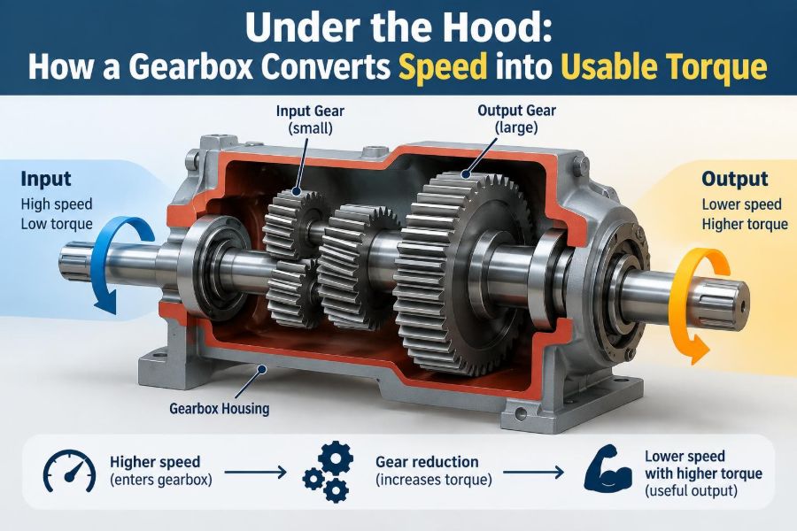
The gearbox is the mechanical interpreter between those needs. It changes rotational speed and torque so that available power becomes useful motion rather than wheelspin, stalling, overheating, or an impractically large motor.
Understanding that exchange makes gear ratios easier to calculate, select, troubleshoot, and explain. It also reveals why a gearbox is not a device that creates force from nothing: it rearranges speed and torque within the limits set by power, losses, and component strength.
🔄 The Basic Job of a Gearbox
A gearbox transmits rotary motion from an input shaft to an output shaft while changing the relationship between their speeds and torques. Its defining feature is the gear ratio: the input speed divided by output speed, or equivalently the output torque divided by input torque in an idealized case.
A reduction gearbox makes the output turn slower and, usually, deliver more torque. A speed-increasing gearbox does the reverse. Many practical gearboxes also change shaft direction, distribute power to multiple outputs, or allow selectable ratios.
🧭 Speed, Torque, and Power Are Different Quantities
Confusing these three terms causes most gearbox misunderstandings. Speed is how fast a shaft rotates, commonly expressed in revolutions per minute (rpm). Torque is twisting moment, commonly measured in newton-metres (N·m).
Power describes the rate at which work is done. For rotating equipment, mechanical power equals torque multiplied by angular speed: P = Tω. At a given power, reducing angular speed permits higher torque; increasing speed requires lower torque.
This is why a low gear helps launch a loaded truck but does not give its engine limitless power. It lets the engine operate at a speed where it can supply power effectively while multiplying torque at the wheels.
⚖️ The Trade-Off That Governs Every Gear Set
Imagine turning a small gear that meshes with a gear twice its diameter. The small gear must turn twice to rotate the larger gear once. The larger gear receives roughly twice the torque, but it runs at half the speed.
That exchange follows conservation of energy. In a perfect, lossless gearbox, input power equals output power. Real gearboxes lose some energy through tooth friction, bearing friction, lubricant churning, seals, and windage, so output power is always slightly lower.
The key rule is simple: gears trade speed for torque; they do not manufacture power.
🦷 Why Tooth Counts Determine Ratio
For two externally meshing gears, the ratio is determined by tooth count. If a 20-tooth pinion drives a 60-tooth gear, the driven gear rotates once for every three rotations of the pinion. The reduction ratio is 3:1.
The same relationship can be written as:
speed reduction = driven gear teeth / driving gear teeth
Because mating gears have the same tooth pitch, a larger tooth count also means a larger pitch diameter. Counting teeth is generally more reliable than estimating diameters from a drawing or a physical assembly.
📐 A Simple Ratio Calculation
Suppose a motor runs at 1,800 rpm and drives a 72-tooth gear through a 24-tooth pinion. The ratio is 72 / 24 = 3, so the output speed is 1,800 / 3 = 600 rpm.
If the motor provides 10 N·m and losses are ignored, output torque is 10 × 3 = 30 N·m. With a realistic efficiency assumption, the usable output torque is lower. At 90% efficiency, for example, it would be about 27 N·m.
This calculation is hypothetical, but the method applies directly to many single-stage drives.
🧮 Including Efficiency in Torque Estimates
Efficiency matters whenever a design must meet a real load requirement. A common first estimate is:
output torque = input torque × gear ratio × efficiency
Efficiency is expressed as a decimal. A value of 0.95 represents 95% efficiency. Actual efficiency depends on gear type, load, lubrication, surface condition, temperature, bearing losses, and operating speed.
A catalog rating, test result, or manufacturer data is preferable to a generic efficiency value for final design. Losses also become heat, which can limit continuous duty even when the gears are strong enough.
↔️ Direction Changes at a Gear Mesh
Two external spur gears rotate in opposite directions. Add a third gear between them and the final output rotates in the same direction as the input. That middle gear is called an idler gear.
An idler changes direction and center distance, but it does not change the overall ratio when it is merely between the driver and driven gears. The overall ratio still depends on the first driving gear and final driven gear tooth counts.
Direction is not a minor detail: a pump, conveyor, fan, or screw mechanism may work poorly—or be damaged—if driven backward.
🔗 Multi-Stage Reduction for Large Ratios
Very large reductions are often divided across two or more stages rather than made with one huge gear and one tiny pinion. If a first stage reduces 3:1 and a second reduces 4:1, the total reduction is 3 × 4 = 12:1.
Multi-stage designs keep gear diameters practical and can distribute loads more effectively. However, every stage adds bearings, meshes, losses, cost, packaging constraints, and potential backlash.
When calculating a compound gearbox, multiply the individual stage ratios and efficiencies. Do not add ratios together.
🧱 Spur Gears: The Straightforward Starting Point
Spur gears have straight teeth parallel to the shaft axis. They are easy to visualize, comparatively simple to manufacture, and widely used in low-to-moderate-speed machinery where parallel shafts are appropriate.
As a spur tooth engages, contact begins suddenly across its face. This can make spur gear sets noisier at high speeds than helical alternatives. Accurate alignment, adequate tooth strength, and proper lubrication remain essential despite their apparent simplicity.
🌀 Helical Gears: Smoother but More Demanding
Helical gear teeth are angled. Engagement begins gradually and spreads across more than one tooth, which often produces smoother, quieter operation and higher load capacity for a given package.
The tooth angle also creates axial thrust, a force along the shaft. Bearings and housing structure must absorb that force. Double-helical arrangements can balance thrust, but they are more complex to manufacture and assemble.
Helical gears are common where refinement, speed capability, and load sharing justify the added design attention.
📐 Bevel Gears for Intersecting Shafts
Bevel gears transmit power between shafts that intersect, often at 90 degrees. Their conical geometry changes the direction of rotation while providing a selected speed ratio.
They appear in right-angle drives, differential systems, and machinery with compact directional layouts. Mounting accuracy is especially important because incorrect contact patterns concentrate stress near a tooth edge.
Straight bevel gears can be noisy; spiral bevel gears offer more gradual engagement but require careful setup. Their geometry should not be treated like a simple pair of spur gears.
🐛 Worm Gears and Their Special Behavior
A worm gearbox uses a screw-like worm to drive a worm wheel, usually at a right angle. It can provide substantial reduction in a compact space, making it useful for positioning equipment, lifts, and rotary actuators.
Its sliding contact produces more friction than the rolling-dominant contact of well-designed spur or helical gears. Efficiency can vary significantly with lead angle, materials, lubrication, load, and speed; heat deserves close attention.
Some worm arrangements resist being driven backward, a behavior often called self-locking. This must never be assumed as a safety brake without verification under actual conditions.
🌐 Planetary Gears Pack Torque Compactly
A planetary set has a central sun gear, several planet gears, an outer ring gear, and a carrier supporting the planets. Different choices of fixed, input, and output member create different ratios and directions.
Because multiple planets share the load and the geometry is coaxial, planetary gearboxes can deliver high torque density in compact packages. They are widely used in automatic transmissions, robotics, aerospace equipment, and servo drives.
The trade-off is analytical and manufacturing complexity. Clearances, load sharing, bearing support, and assembly accuracy all influence performance.
🚗 Why Vehicles Need Multiple Ratios
A vehicle at rest needs substantial wheel torque to overcome inertia, gradients, rolling resistance, and driveline losses. At highway speed, that same reduction would make the engine spin excessively fast. Multiple ratios solve both problems.
Low gears multiply wheel torque for launch and climbing. Higher gears reduce engine speed at a given road speed, often improving noise, fuel consumption, and thermal comfort when load permits.
Electric vehicles also use gear reduction, although many use a fixed ratio because electric motors can operate over a wider useful speed range than conventional engines.
🚲 The Bicycle Analogy, Used Carefully
A bicycle is an excellent demonstration of ratio selection. A small front chainring driving a large rear sprocket is a low gear: high wheel torque, low wheel speed for a given cadence. A large front chainring and small rear sprocket create a high gear.
The rider supplies roughly the same limited leg power. Changing gear does not eliminate the hill; it changes pedal force and cadence into a combination the rider can sustain.
Unlike a sealed gearbox, a chain drive uses sprockets and a flexible chain, but the speed-torque logic is the same.
🏭 Matching a Motor to Its Load
Gear ratio selection starts with the load. A conveyor may need specified belt speed and starting torque. A mixer may need low output speed with resistance that changes as material thickens. A robot joint may prioritize positional stiffness and compactness.
Work backward from required output speed and torque, then account for acceleration, duty cycle, friction, external forces, and expected overloads. The selected motor must provide adequate torque across its operating speed range, not merely at one favorable point.
A ratio that looks correct in steady-state calculations can still fail during starts, stops, reversals, or impacts.
📈 Reflected Inertia Changes What the Motor Feels
When a load is viewed through a reduction gearbox, its rotational inertia is reflected back to the motor by the square of the ratio. In simplified form, a load inertia at the output appears at the input as Jload / N², where N is reduction ratio.
This can make a heavy load easier for a motor to accelerate. But more reduction also lowers output speed and can increase backlash, compliance, or transmission losses.
Servo systems often balance inertia matching, response speed, torque reserve, and mechanical stiffness rather than chasing the largest possible ratio.
⏱️ Starting Torque and Transient Loads
Steady torque is only part of the design problem. A machine may need extra torque to accelerate rotating mass, break static friction, lift a load, crush material, or survive a sudden jam.
These transient loads can exceed normal running torque by a wide margin depending on the application. Gear teeth, shafts, keys, couplings, bearings, and housings all need evaluation for the relevant peak conditions.
A gearbox rated for continuous torque is not automatically suitable for repeated shock loading. Duty cycle and load spectrum matter.
🌡️ Where Lost Power Goes: Heat
Every watt lost inside a gearbox becomes heat. At light loads this may be modest; at high torque, high speed, or continuous operation, thermal capacity can become the limiting factor before tooth strength does.
Oil carries heat away from contact surfaces and into the housing. Housing area, airflow, ambient temperature, oil level, churning losses, and any external cooling system determine whether heat can escape fast enough.
Overheating can reduce lubricant viscosity, accelerate oxidation, damage seals, and shorten bearing and gear life. Temperature is therefore a useful condition-monitoring signal, not just an inconvenience.
🛢️ Lubrication Protects the Gear Mesh
Lubricant separates surfaces, reduces friction, transports heat, and helps protect metal from corrosion. The required viscosity and additive package depend on gear type, speed, load, temperature, and manufacturer guidance.
Too little oil can cause scuffing and rapid wear. Too much can increase churning losses and heat. Contamination from dirt, water, or wear particles can damage highly loaded contacts and bearings.
- Use the specified lubricant grade and compatible seals.
- Check level using the prescribed machine position and temperature condition.
- Investigate unusual debris, odor, discoloration, or repeated leakage.
🎯 Backlash Is Clearance, Not Automatically a Defect
Backlash is the small clearance between mating teeth measured as lost motion when rotation reverses. Some backlash is necessary to accommodate lubrication, manufacturing variation, thermal expansion, and reliable meshing.
Too much backlash can reduce positioning accuracy, create impact during reversals, and produce noise. Too little can cause binding, heat, and premature failure as components expand or deflect under load.
Precision motion systems may use carefully controlled backlash, preload methods, or alternative transmission arrangements. The correct value depends on the application, not on a universal “as little as possible” rule.
📏 Alignment Controls Tooth Contact
Gears are designed to carry load over a planned contact area. Shaft deflection, housing distortion, bearing clearance, mounting errors, or thermal growth can shift that contact toward one tooth edge.
Edge loading raises local stress and can initiate pitting, wear, or tooth fracture. Larger industrial gearboxes may use contact-pattern checks, stiffness analysis, or intentional tooth modifications to maintain favorable contact under working load.
Good alignment begins with a rigid foundation and continues through coupling alignment, correct fastener torque, and bearing condition.
🔊 Noise and Vibration Offer Clues
A healthy gearbox produces a characteristic sound, but changes matter more than absolute loudness. Whine may reflect normal gear mesh frequency, while a new rumble, repeating knock, or harsh vibration can point to wear, misalignment, bearing damage, loose mounting, or inadequate lubrication.
Vibration analysis can identify frequencies related to shaft rotation, gear mesh, and bearing elements. It is a powerful diagnostic tool when measurements are collected consistently and interpreted alongside operating conditions.
Do not diagnose solely by sound. Guarding, load, mounting structure, and adjacent machinery can all alter what an operator hears.
🧪 Common Gear Damage Modes
Gear teeth can fail in several ways, and the visible pattern often helps narrow the cause:
- Pitting: small fatigue pits caused by repeated contact stress.
- Scuffing: surface damage from lubricant-film breakdown and sliding contact.
- Wear: gradual material loss, often worsened by contamination or poor lubrication.
- Tooth breakage: overload, fatigue cracking, impact, or severe misalignment.
Failure analysis should include load history, lubricant condition, alignment, bearing support, and the driven machine. Replacing a damaged gear without correcting its cause invites a repeat failure.
🧰 Choosing Ratio Is More Than Dividing RPM
A first-pass ratio comes from desired input and output speeds. A viable final ratio also must satisfy torque capacity, thermal rating, acceptable inertia, package size, shaft loads, backlash, duty cycle, noise limits, and available motor speed.
For an industrial reducer, compare both rated output torque and permitted overhung or axial shaft load. A belt pulley or sprocket mounted on the output shaft can impose loads that are independent of transmitted torque.
Catalog values are usually conditional. Check mounting orientation, service factor assumptions, lubricant, ambient temperature, and operating profile before treating a rating as directly applicable.
⚠️ Service Factors Are Not a Substitute for Load Data
A service factor is a design allowance used to account for application severity and uncertainty. It can be useful when selecting equipment, especially where starts, shocks, or long operating hours differ from nominal conditions.
But it is not a magic multiplier that repairs an unknown load case. If a machine experiences known impacts, frequent reversals, or a heavy vertical load, model those conditions explicitly where possible.
A conservatively chosen gearbox may still be unsuitable if its brake, mounting, lubrication, or supporting structure is overlooked.
🧑🔧 Practical Maintenance Habits
Reliable gearbox maintenance is usually disciplined rather than dramatic. Follow the equipment manufacturer’s inspection and lubricant intervals, and adapt them when duty, contamination, or operating temperature is unusually severe.
- Look for leaks, loose fasteners, damaged breathers, and deteriorated guards.
- Record temperature, vibration, noise, and oil observations over time.
- Keep breathers, seals, and surrounding areas clean to limit contamination.
- Before opening or servicing equipment, isolate energy and secure any suspended or rotating load.
Maintenance requirements vary by gearbox design. Site procedures and manufacturer instructions should take priority over generic advice.
🚫 Mistakes That Lead to Poor Gearbox Performance
One common mistake is selecting a reducer only by its ratio and nominal torque rating. Another is assuming the motor’s nameplate power alone proves suitability, without checking speed, starting conditions, and thermal duty.
Installing a gearbox with an unsupported output shaft, incorrect oil level, incompatible lubricant, or misaligned coupling can erase the benefit of good component selection. So can ignoring reversing loads in an application that changes direction frequently.
The practical lesson is to treat the gearbox as part of a drive system, not as an isolated black box.
🔍 A Compact Design-Check Sequence
Before finalizing a gearbox choice, move through the problem in a deliberate order:
- Define required output speed, torque, motion profile, and direction.
- Estimate steady, starting, accelerating, and shock loads.
- Select a tentative ratio from motor and output speed needs.
- Check torque, thermal, shaft-load, life, and mounting limits.
- Verify backlash, efficiency, noise, and control requirements.
- Confirm lubrication, guarding, braking, and maintenance access.
This sequence does not replace detailed engineering analysis, but it prevents many avoidable omissions early in a project.
🧠 The Core Principle to Remember
A gearbox makes a power source more useful by matching its speed and torque to the task. Low ratios favor output speed; high reduction ratios favor output torque. The available output power remains bounded by input power and reduced by losses.
Successful gearbox use depends on more than tooth counts. Gear type, efficiency, heat, stiffness, alignment, lubrication, transient loading, and maintenance determine whether a calculated ratio becomes a dependable machine.
When evaluating any drive, ask two connected questions: how fast must the output turn, and how much torque must it deliver throughout the real operating cycle? The gearbox is the mechanism that negotiates between those answers.
A gearbox converts speed into usable torque by making a controlled trade—not by creating energy—and good engineering means managing every consequence of that trade. ⚙️🔧📈