
A maintenance engineer is holding a replacement bracket that would take weeks to machine from billet. A supplier says the same geometry can be printed in metal within days, with less material waste and several parts combined into one. The obvious question is not whether it looks like a metal part. It is whether it can safely carry the load.
That question becomes sharper when the part sits in a pressure system, aircraft, production machine, medical device, or powertrain. A cracked decorative component is inconvenient. A cracked load-bearing component can stop a line, damage equipment, or create a safety hazard.
Metal additive manufacturing has moved well beyond prototypes. Yet “3D-printed metal” is not a single material condition, and strength is only one piece of engineering suitability. The printing process, alloy, orientation, heat treatment, inspection plan, and service environment all affect the answer.
For many applications, a properly designed and qualified printed metal component can be highly capable. For others, conventional forging, casting, machining, or a hybrid route remains the more defensible choice. Knowing the difference is the real engineering task.
🔩 The short answer: sometimes, with evidence
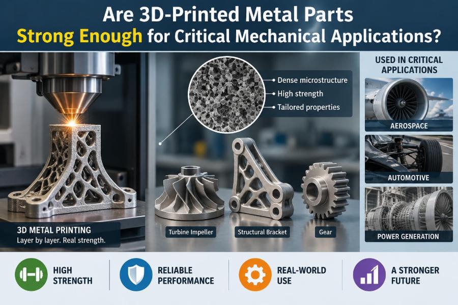
Yes, metal 3D-printed parts can be strong enough for critical mechanical applications. Some qualified components are already used where low mass, internal complexity, or rapid part consolidation offers a meaningful advantage.
But strength cannot be inferred from the CAD model, an attractive surface finish, or a supplier’s generic material data sheet. A critical part needs a demonstrated process–material–geometry–inspection chain. Change one element, such as powder batch, build orientation, machine settings, or heat treatment, and the resulting properties may change.
The practical answer is therefore conditional: printed metal is suitable when the design requirements are defined, the manufacturing route is controlled, and the finished part is verified for its intended duty.
🧱 What “strong enough” actually means
Engineers use “strength” loosely in conversation, but a component rarely succeeds or fails based on one tensile value. Yield strength is the stress at which permanent deformation begins. Ultimate tensile strength is the highest stress reached during a tensile test before fracture.
A bracket may need stiffness to hold alignment. A rotating part may need fatigue resistance. A hot component may need creep resistance, meaning resistance to slow deformation under sustained load and temperature. A pressure boundary may need leak tightness and fracture resistance.
“Strong enough” means meeting the relevant design limits with appropriate safety margins over the full service life. That includes realistic loads, temperatures, vibration, corrosion, manufacturing variation, and inspection capability.
🖨️ Metal printing is a family of processes
Different metal additive processes create different microstructures, defect risks, sizes, and post-processing needs. Treating them as interchangeable leads to poor material decisions.
| Process family | Basic approach | Typical engineering consideration |
|---|---|---|
| Laser powder bed fusion | A laser selectively melts thin powder layers in a powder bed. | Fine detail and complex features, but residual stress and internal defects require close control. |
| Electron beam powder bed fusion | An electron beam melts powder under vacuum at elevated build temperatures. | Useful for certain reactive alloys; surface finish and feature resolution differ from laser systems. |
| Directed energy deposition | Energy melts wire or powder as material is deposited. | Suited to repair and larger builds; machining is often needed for final accuracy. |
| Binder jetting | A binder shapes powder, followed by sintering. | Production potential is attractive, but shrinkage and density control are central concerns. |
Each route needs its own qualified parameter window. A result obtained from one process should not be casually applied to another.
⚡ Why the process creates unusual material behavior
In powder bed fusion, a tiny melt pool forms and solidifies extremely quickly as the energy source moves across each layer. The next layer reheats regions beneath it. This repeated thermal cycling is very different from the thermal history of a wrought bar or a conventional casting.
The outcome can include fine microstructural features, direction-dependent grains, local composition changes, and residual stresses. These are not automatically defects; they are features of the process that must be understood and managed.
It helps to view a printed part not as “metal shaped by a printer,” but as a material made through a tightly sequenced thermal manufacturing process.
🧭 Build orientation affects the result
A printed component has a build direction, and that direction can influence properties. Layers, scan strategy, thermal gradients, and support placement may produce anisotropy: different behavior when tested parallel and perpendicular to the build direction.
For a simple tensile coupon, this may appear as a difference in elongation or fatigue performance. In a real part, it matters where the principal loads travel. A designer should not orient a component only to minimize supports or shorten build time.
Load paths, critical holes, thin walls, surface accessibility, distortion risk, and inspection access all belong in orientation planning. The best orientation is usually a compromise, not a single-rule answer.
🕳️ Porosity is small but mechanically significant
Porosity refers to voids inside a metal part. Some pores are nearly spherical; others are irregular lack-of-fusion defects caused when adjacent melt tracks do not fully join. The latter are often more concerning because their sharp shape can concentrate stress.
Under static loading, a small internal pore may have little effect if the remaining section is ample. Under cyclic loading, however, a pore near a highly stressed region can become the starting point for a fatigue crack.
Density alone is not enough. Engineers also need to consider defect size, shape, location, orientation relative to stress, and the likelihood that inspection can detect unacceptable flaws.
🔍 Lack of fusion deserves special attention
Lack of fusion can arise from insufficient energy, poor overlap between melt tracks, unsuitable layer conditions, or local process instability. It may resemble a thin, irregular crack buried in the material rather than a rounded gas pore.
That geometry makes it an effective stress raiser. It can reduce ductility and create a preferential path for crack growth, particularly in fatigue-sensitive applications.
Preventing lack of fusion is better than attempting to screen it out afterward. Stable machine parameters, powder condition, layer recoating quality, calibration, and monitoring are fundamental controls.
🌡️ Residual stress can distort and weaken a design
As a printed layer cools, it contracts while remaining attached to hotter or more constrained material. This creates residual stress: stress locked into the part even when no external load is applied.
Residual stress can cause distortion during the build, cracking in susceptible alloys, or movement when the part is cut from the build plate. It may also combine unfavorably with service loads and affect fatigue behavior.
Supports, scan strategies, preheating, stress-relief heat treatment, and thoughtful geometry all help. The important point is that residual stress is a design-and-process issue, not merely an inconvenient finishing detail.
🔥 Heat treatment is part of manufacturing, not an optional extra
A printed alloy commonly needs heat treatment after building. Stress relief reduces locked-in stress. Solution treatment and aging can develop desired phases in precipitation-strengthened alloys. Annealing can alter ductility and microstructural stability.
Hot isostatic pressing, often called HIP, combines elevated temperature and high gas pressure to close certain internal voids and improve material continuity. It can be valuable for fatigue-critical parts, although it does not erase every defect type or replace sound process control.
Heat treatment schedules must be established for the specific alloy and printing route. Applying a schedule intended for wrought stock may not produce the intended printed-part properties.
🧪 Tensile tests answer only part of the question
Tensile testing provides useful baseline data: yield strength, ultimate strength, elongation, and reduction in area. It is essential, but it is a controlled test of a standardized specimen under a steadily increasing load.
Many critical components see something else entirely: millions of load cycles, contact stresses, thermal gradients, impact, or a corrosive fluid. A part can show impressive tensile strength yet perform poorly in a fatigue condition driven by rough surfaces or internal defects.
Use tensile results to establish material capability, not as a universal certificate of component reliability.
🔄 Fatigue is often the governing concern
Fatigue is progressive damage caused by repeated loading. A stress level below the static yield strength can still initiate and grow a crack after enough cycles. This is why vibration-prone brackets, shafts, impellers, and actuator components deserve especially careful evaluation.
Printed metal can achieve useful fatigue performance, particularly when defects are controlled and surfaces are finished appropriately. But fatigue data are sensitive to specimen geometry, build orientation, surface condition, stress ratio, environment, and post-processing.
A generic fatigue curve is not a substitute for evidence that represents the component’s material state and expected loading. For truly critical duties, representative testing and conservative design assumptions are often necessary.
🏔️ Surface roughness acts like a field of tiny notches
As-built additive surfaces commonly contain partially fused particles, stair-step layer features, and local roughness. Under tensile loading these may be tolerable. Under fatigue loading, they can act as numerous micro-notches where cracks begin.
Machining, grinding, polishing, abrasive flow finishing, or other validated finishing methods can improve critical surfaces. The correct method depends on access, geometry, dimensional tolerance, and whether internal channels also need treatment.
Do not assume a smoother-looking surface automatically has better fatigue performance. The process must avoid introducing damage, excessive material removal, or unfavorable residual stresses.
🧬 Microstructure determines more than hardness
Microstructure describes features inside the metal, including grains, phases, precipitates, and segregation patterns. These features influence yield strength, ductility, toughness, corrosion behavior, and high-temperature stability.
Rapid solidification can produce microstructures that differ substantially from cast or wrought forms of the same nominal alloy. That can be helpful, but it also means conventional expectations need confirmation.
For example, an alloy selected because it is familiar in forged form should not be assumed to behave identically after printing. Material specification must identify the manufacturing condition, not just the chemical alloy name.
🧲 Alloy choice changes the risk profile
Common printable engineering alloys include stainless steels, tool steels, titanium alloys, nickel-based superalloys, aluminum alloys, and cobalt-chromium alloys. Their printability and post-processing response vary widely.
Some alloys are relatively forgiving within established processes. Others are prone to hot cracking, oxidation, distortion, or demanding thermal treatment. High strength can also arrive with reduced ductility or more difficult machining.
Select the alloy from the service requirements first: temperature, environment, load mode, stiffness, wear, mass, and joining needs. Then confirm that a controlled additive route exists for that alloy and part geometry.
📐 Design for additive manufacturing is not ordinary CAD
Simply printing a component designed for machining usually captures little of additive manufacturing’s value and may create unnecessary problems. Design for additive manufacturing considers overhangs, support removal, powder evacuation, thermal mass changes, tolerances, and finishing access from the start.
The best opportunities often involve part consolidation, topology optimization, conformal cooling, or internal passages that cannot be made conventionally. These features must still allow powder removal and inspection.
A useful question is: does the geometry solve a real system-level problem? Reducing assembly interfaces or improving heat transfer can justify process complexity more convincingly than printing a conventional shape merely because it is printable.
🧠 Topology optimization needs manufacturing constraints
Topology optimization uses computational methods to remove material from lightly loaded regions while retaining material along efficient load paths. It can create organic-looking forms that are well suited to additive manufacturing.
However, the raw optimized shape may contain thin members, sharp transitions, inaccessible cavities, or unsupported overhangs. These features may be difficult to print, inspect, finish, or protect from fatigue.
Manufacturing constraints should be included early, followed by engineering review. A lightweight shape is only successful if its minimum thicknesses, transitions, interfaces, and allowable defects are compatible with the production route.
📏 Tolerances still require machining strategy
Additive manufacturing is not a replacement for precision machining in every location. Holes, bearing seats, sealing faces, threads, and mating datums often require subtractive finishing after printing.
Good designs reserve machining stock where needed and establish reliable datum surfaces. They also account for distortion and the fact that a complex printed shape may be difficult to grip in a fixture.
Ignoring finishing strategy late in development is a common source of cost and schedule problems. The manufacturing plan should show how the part will be held, measured, machined, and re-inspected.
🧱 Supports are structural tools with consequences
Supports anchor overhangs, conduct heat away from local regions, and resist distortion during printing. They are not merely disposable scaffolding.
Their placement can affect surface condition, local thermal history, and ease of post-processing. A support under an internal channel may be impossible to remove; a support on a functional face can turn a simple part into a difficult machining job.
Designers should review support strategy alongside the part geometry. In some cases, splitting a part or changing an angle slightly creates a more reliable and inspectable solution than forcing a support-heavy build.
🧹 Powder removal is a safety and reliability issue
Internal cavities and channels can trap unused powder. This may add unwanted mass, obstruct fluid flow, contaminate a system, or create handling concerns depending on the material and application.
Powder escape paths need sufficient size, sensible placement, and a plan for verification. Complex lattices and manifolds are especially likely to challenge cleaning.
For a hypothetical cooled tooling insert, a beautifully routed internal channel is not useful if residual powder blocks a branch or cannot be demonstrated to have been removed. Design the cleaning path, not only the flow path.
👁️ Inspection must match the failure risk
Inspection cannot create quality, but it can provide evidence that the process remained within control and that the finished part meets acceptance requirements. The needed methods depend on the component’s function and credible defect modes.
- Dimensional inspection checks interfaces, wall thicknesses, and critical geometry.
- Computed tomography can reveal internal geometry and certain internal defects, though resolution and part size impose limits.
- Surface methods can help find accessible cracks or discontinuities.
- Metallography and mechanical coupons provide deeper process validation, often through representative builds rather than every production part.
No single method sees everything. An inspection plan should state what each method can detect, what it cannot detect, and why that coverage is adequate.
📡 In-process monitoring is useful, not magical
Many additive machines record information such as optical emissions, melt-pool signals, layer images, chamber conditions, or recoater behavior. These records can flag anomalies and support traceability.
Monitoring data do not automatically prove that every cubic millimeter meets requirements. Turning sensor signals into accepted quality decisions requires correlation with destructive testing, inspection, and a validated process model.
Used well, monitoring helps detect departures early and reduces reliance on guesswork. Used carelessly, it can create false confidence from large quantities of poorly interpreted data.
📜 Qualification means controlling the whole route
Qualification is the structured demonstration that a manufacturing route repeatedly produces acceptable parts. It includes machine configuration, parameter sets, powder handling, operator procedures, build layout, post-processing, inspection, and records.
For a safety-critical application, qualification usually distinguishes between material allowables, process qualification, and part qualification. A material may be capable in principle, while a particular geometry or build arrangement still needs separate evidence.
This can feel burdensome compared with ordering a prototype. It is also why the transition from one successful sample to dependable production is the central challenge in critical additive manufacturing.
🧾 Traceability protects decisions made years later
A robust record links each part to its design revision, powder lot and reuse history, machine, parameter set, build file, operator actions, thermal cycles, finishing operations, and inspection results.
Traceability supports troubleshooting if a problem appears in service. It also prevents a subtle but serious error: treating two visually similar printed parts as equivalent when their manufacturing histories differ.
For noncritical prototypes, documentation can be light. As consequence of failure rises, traceability becomes an engineering control rather than administrative overhead.
🌧️ Service environment can overturn a good test result
A specimen tested in a laboratory may not represent a part exposed to salt, humidity, elevated temperature, hydraulic fluid, abrasive particles, or cleaning chemicals. Corrosion can interact with cyclic stress and accelerate crack initiation.
High temperatures can reduce strength, alter microstructure, or activate creep. Low temperatures can reduce toughness in some material conditions. Wear and fretting at interfaces can also dominate local damage.
Qualification should reproduce the most relevant service conditions where practical. At minimum, the design review should identify which environmental mechanisms could invalidate room-temperature test assumptions.
🛠️ Joining and repairs need their own validation
Printed components may be bolted, welded, brazed, bonded, or pressed into assemblies. These joints can become the weakest or most variable region, especially if the printed surface condition is not prepared correctly.
Welding can add heat, residual stress, and microstructural change. Machined interfaces may improve fit-up but introduce their own tolerance requirements. Repair by directed energy deposition can be valuable, yet the repaired zone and heat-affected region need assessment.
Evaluate the assembled system, not just the standalone printed part. Load transfer, joint preload, galvanic compatibility, sealing, and accessibility for inspection all matter.
⚖️ Compare additive routes with conventional manufacturing fairly
Forging often provides excellent fatigue performance and well-understood properties. Machining offers tight tolerances and established inspection. Casting can be economical for suitable shapes and volumes, but it has its own porosity and quality-control challenges.
Additive manufacturing can reduce assembly count, shorten supply chains, lower material waste for costly alloys, and enable shapes that conventional tools cannot reach. It may also have slower build rates, higher finishing needs, and a more demanding qualification burden.
The correct comparison is not “printed versus traditional” in the abstract. Compare complete routes for a specific component: performance, production volume, lead time, inspection, lifecycle cost, failure consequence, and supply resilience.
💰 The business case is rarely just piece price
A printed part may cost more than a machined equivalent at the component level but save money by eliminating fasteners, assembly labor, leak paths, tooling, or inventory. Conversely, an impressive lightweight design may not justify itself if it needs extensive hand finishing and difficult inspection.
Critical applications should include the cost of qualification, coupon testing, nondestructive examination, heat treatment, machining, documentation, and possible yield loss. Leaving these out creates an unrealistic estimate.
Volume matters, but so does complexity. A low-volume, high-value component with a difficult supply chain may be a stronger additive candidate than a simple component made in very high quantities.
🚫 Common mistakes when evaluating printed metal
- Equating high tensile strength with durability: fatigue, toughness, and environment may govern instead.
- Using generic supplier data as part-specific evidence: geometry and process condition affect results.
- Leaving post-processing until the end: supports, heat treatment, machining, and cleaning shape the design.
- Designing sealed internal spaces: trapped powder and inspection limitations can make them unacceptable.
- Assuming inspection finds every defect: each method has resolution and access limits.
- Changing settings casually after qualification: apparently minor changes can invalidate prior evidence.
Most of these failures originate at the handoff between design, materials, manufacturing, and quality. Cross-functional review early in the project is far cheaper than solving them after the first build.
✅ A practical screening workflow
Before committing a critical component to metal additive manufacturing, use a staged decision process rather than a yes-or-no debate.
- Define function, load cases, life target, environment, interfaces, and consequence of failure.
- Identify the governing failure modes: static yielding, fatigue, fracture, creep, wear, leakage, or corrosion.
- Select candidate alloys and additive processes based on service needs and known manufacturing capability.
- Design the geometry, orientation, supports, powder removal, machining access, and inspection access together.
- Specify post-processing and develop representative test and inspection evidence.
- Qualify the controlled production route, then maintain it through disciplined change control.
This workflow does not remove uncertainty. It makes uncertainty visible early enough to manage.
🏭 Where printed metal is particularly compelling
Additive manufacturing is often attractive when geometry drives value. Examples include conformal cooling channels in tooling, lightweight structures with carefully managed load paths, flow components with integrated passages, and replacements for assemblies with many interfaces.
It can also be useful when lead time or obsolescence is the problem, provided the qualification effort is appropriate. A replacement part is not automatically safe to reverse engineer and print; its original material condition and failure history still matter.
The strongest candidates have a clear reason to use additive manufacturing beyond novelty. They use complexity to improve system performance, reliability, maintainability, or supply security.
🧱 Where conventional manufacturing may remain better
A simple, high-volume part with generous material availability and mature forging or machining routes may gain little from printing. The conventional option may deliver lower cost, better surface condition, faster throughput, and more established material allowables.
Extremely demanding fatigue applications can also favor conventional wrought forms unless additive process capability and post-processing have been rigorously established. Very large components may face build-envelope, distortion, and inspection constraints.
Choosing conventional manufacturing is not a failure of innovation. It can be the most technically responsible choice when the additive advantage does not outweigh the added process risk.
🎯 The core principle: capability must be demonstrated
Metal additive manufacturing is capable of producing parts for demanding mechanical duties, but capability is not a property of the printer alone. It emerges from the alloy, process parameters, geometry, orientation, post-processing, surface condition, inspection, and intended service.
The most reliable teams start with failure modes, not with a preferred manufacturing technology. They ask what could crack, deform, leak, corrode, wear, or become impossible to inspect—and build controls around those answers.
That mindset avoids both extremes: dismissing printed metal as weak by definition, and assuming complex geometry makes it ready for critical service. Both views skip the engineering evidence that matters.
3D-printed metal parts can be strong enough for critical applications when the entire manufacturing and verification route—not merely the final shape—is designed, controlled, and qualified for the job. That is the standard worth applying whether the part is printed, forged, cast, or machined. ⚙️🔍🏗️