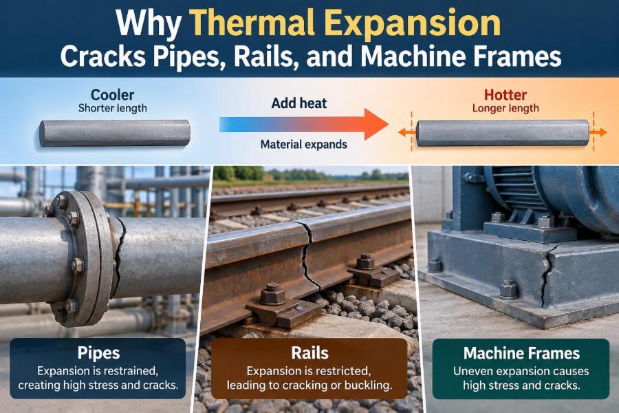

A steam line is started after a cold night. A few minutes later, it is hotter, longer, and pushing against supports that seemed perfectly harmless during installation. If the route cannot accommodate that change, the pipe does not simply “settle”; stress begins to build.
On a railway, a similar process can turn a carefully aligned track into a lateral buckle during hot weather. In a machine shop, a rigid frame can drift out of alignment as one side warms faster than the other, affecting accuracy long before anyone sees visible damage.
Thermal expansion is often introduced as a simple formula in materials science. In real equipment, it is a design condition that influences clearances, anchors, joints, supports, tolerances, startup procedures, and inspection plans.
The important question is not whether a component expands. It almost always does. The engineering question is where the thermal movement goes, and what happens if it has nowhere safe to go. 🌡️
🌡️ 1. Thermal expansion is ordinary material behavior
Most solids increase in length when their temperature rises and decrease in length when they cool. Heating raises atomic vibration energy, increasing the average spacing between atoms or molecules.
This change is usually small in any one metre of material. Across a long pipe run, rail, beam, or machine bed, however, small strain becomes meaningful movement.
📏 2. The basic expansion equation
For a uniform member free to move, linear thermal expansion is estimated with ΔL = αLΔT. Here, ΔL is the length change, α is the coefficient of linear thermal expansion, L is original length, and ΔT is the temperature change.
The equation predicts displacement, not stress. Stress enters the problem only when constraints, temperature gradients, friction, or connected components resist that displacement.
🧱 3. Length turns a small strain into a large movement
Consider a steel member 30 m long that experiences a temperature increase of 50°C. Using a typical steel expansion coefficient near 12 × 10-6 per °C, its free expansion is about 18 mm.
Eighteen millimetres may sound modest, but it can exceed a seal’s travel, close a deliberately small gap, overload a support, or shift a precision alignment. Long straight runs demand particular attention.
🔒 4. Restraint converts expansion into stress
If a uniformly heated bar is completely prevented from expanding, it develops compressive thermal stress. In the simplified elastic case, that stress is approximated by σ = EαΔT, where E is Young’s modulus.
This result explains why apparently rigid supports can be dangerous. A high-modulus material such as steel can develop substantial stress from a temperature change even when its free movement would have been only a few millimetres.
Real systems are rarely perfectly fixed, so load sharing, local bending, friction, and yielding matter. The simple expression remains valuable because it reveals the mechanism. ⚙️
🧭 5. A component is rarely free or fully fixed
Actual structures occupy the space between ideal extremes. Pipe supports may slide until friction is overcome, then stick. Bolted connections may slip slightly. Soil, insulation, clamps, and neighboring equipment can add restraint that was not obvious on a drawing.
Good analysis identifies the true boundary conditions rather than assuming that a “guide,” “anchor,” or “support” behaves exactly as its name suggests.
🔥 6. Temperature change is not always uniform
A member can be hot on one face and cool on the other, or hot at one end and cold at the other. These temperature gradients create differential expansion within the same component.
Instead of only changing length, the part may bend, twist, or develop localized stress. A uniform-temperature calculation cannot capture these effects.
🌡️ 7. Through-thickness gradients cause bending
When the top surface of a plate heats before the bottom, the top tries to become longer. Because both surfaces are connected, the plate curves.
This is a common concern in welded structures, furnace fixtures, brake components, thick machine bases, and equipment exposed to one-sided radiant heat. Restraint of that curvature adds further stress.
🧪 8. Material choice changes the amount of movement
Different materials have different expansion coefficients. Aluminum generally expands more per degree than carbon steel, while some specialty alloys and ceramics expand less.
| Material group | Relative thermal expansion | Typical design implication |
|---|---|---|
| Carbon and low-alloy steels | Moderate | Movement still becomes important over long runs and wide temperature ranges. |
| Aluminum alloys | Higher than steel | Clearances, joints, and mixed-material attachments need added attention. |
| Stainless steels | Often higher than carbon steel | Hot piping and fabricated equipment may need greater flexibility than expected. |
| Concrete and masonry | Moderate but variable | Cracking behavior also depends strongly on moisture, restraint, and reinforcement. |
| Polymers | Often relatively high | Large movement and temperature-dependent stiffness can govern joint design. |
Values vary by alloy, temperature, orientation, and product form. Engineers should use relevant material data for the actual operating range rather than relying only on broad comparisons.
🧩 9. Mixed materials create differential expansion
Joining aluminum to steel, a ceramic liner to a metal shell, or a polymer seal to a metal housing creates a compatibility problem. Each material wants to change size by a different amount.
If the joint is rigid, the mismatch becomes stress. If the interface can slide, flex, or use a compliant layer, the assembly can often accommodate the difference safely.
🚰 10. Pipes expand along their routes
Hot pipes do not only move outward from their center; they follow the stiffness and restraints of the route. An anchored pipe segment expands away from its anchor, while guided sections are intended to move predominantly in one direction.
Every elbow, branch, valve, reducer, and connection to equipment influences the load path. Pipe flexibility is therefore a system problem, not merely a property of one straight spool.
🧷 11. Anchors, guides, and supports have different jobs
These terms are often used loosely, but their intended functions differ:
- Anchors restrain movement, often in multiple directions, and transmit thermal loads into structure.
- Guides limit lateral motion while allowing axial travel.
- Resting or sliding supports carry weight while ideally permitting controlled movement.
- Spring supports help manage weight where vertical thermal movement is significant.
A misplaced anchor can force expansion into a nozzle or valve. A missing guide can allow a line to move sideways and create unexpected bending.
↪️ 12. Expansion loops use flexibility instead of force
An expansion loop introduces a deliberate bend in the piping route. As the straight legs grow, the loop flexes, converting some axial movement into bending deformation over a longer length.
The aim is not to eliminate thermal movement. It is to give movement a predictable, low-stress path while keeping loads on equipment connections within acceptable limits.
🪗 13. Bellows can absorb movement, but need discipline
Expansion joints with metallic bellows can accommodate axial, lateral, or angular movement in a compact space. They are useful where a long loop is impractical, but they are not universal fixes.
Bellows are thin, flexible pressure-boundary components. They require correct guides, anchors, pressure thrust management, alignment, movement limits, and protection against damage. Poorly installed bellows can fail quickly because they receive loads they were never meant to carry.
💨 14. Pressure thrust is a separate piping load
In pressurized piping, an expansion joint can experience pressure thrust related to internal pressure acting over an effective area. This load can be large enough to move piping if the system lacks properly designed restraints.
Thermal movement and pressure loading must therefore be considered together. A joint that accommodates expansion may still require a restrained or tied arrangement to manage pressure forces.
💥 15. Why pipes crack near rigid connections
Cracks often appear where flexibility suddenly disappears: at vessel nozzles, pump connections, wall penetrations, clamps, welded attachments, and transitions to heavy valves. These locations combine restraint with geometric stress concentration.
Repeated heating and cooling can turn a local stress range into fatigue damage. A crack may initiate at a weld toe, notch, corrosion pit, or other small imperfection and then grow over many cycles.
🚂 16. Rails face heat-induced compression
Continuous welded rail is intentionally installed and managed so that temperature-related forces remain controlled. When rail temperature rises, restrained rail develops compression rather than simply extending through open joints.
If compressive force becomes excessive relative to track resistance and lateral stability, the track can deform sideways in a thermal buckle. This is not just a rail problem; sleepers, ballast, fasteners, alignment, and maintenance condition all affect stability.
🛤️ 17. Rail neutral temperature matters
Railway engineering uses the idea of a neutral or stress-free rail temperature. At that condition, the rail has neither excessive thermal tension nor compression from temperature difference alone.
If rail is installed, adjusted, or disturbed without controlling its stress state, later weather changes can create undesirable forces. This is why rail handling and maintenance procedures are closely tied to temperature conditions.
🏭 18. Machine frames can lose accuracy before they crack
A machine frame does not need to fracture to suffer from thermal expansion. A few micrometres of relative movement between a spindle, guideway, encoder scale, and workpiece can affect precision machining or measurement.
Heat from motors, bearings, cutting, hydraulic systems, electronics, and sunlight can create uneven temperature fields. Thermal symmetry is often as important as the absolute temperature of the frame.
🎯 19. Differential growth creates alignment errors
Imagine a motor and driven machine mounted on separate supports. If one support warms more than the other, shaft centerlines shift relative to each other, increasing coupling and bearing loads.
Similarly, a bridge-type machine can tilt if its two sides heat differently. Precision systems often use warm-up periods, symmetric layouts, cooling control, and software compensation to reduce these errors.
🔩 20. Bolts can loosen or overload during temperature changes
A bolted joint depends on preload. If a bolt and clamped parts expand by different amounts, heating can change that preload significantly.
For example, a fastener passing through a thick joint may become more or less stretched depending on relative material expansion and temperature distribution. Loss of preload can permit leakage or slip; excess preload can promote yielding, embedment, or fatigue.
🧯 21. Thermal cycling is often worse than one hot event
A single slow temperature change may produce acceptable stress. Repeated cycles can cause fatigue, fretting, seal wear, bolt relaxation, insulation damage, and progressive crack growth.
The relevant issue is frequently the range of stress, not just the peak temperature. Startup, shutdown, batch operation, day-night exposure, and intermittent process flow all create cycles worth evaluating.
⏱️ 22. Fast heating raises the risk
Rapid heating produces steeper temperature gradients because heat needs time to conduct through a component. The surface expands before the interior catches up.
Thick sections, welded assemblies, castings, and lined equipment are especially vulnerable to transient gradients. Controlled ramp rates can reduce thermal shock and give the whole system time to expand more uniformly.
🧊 23. Cooling can be equally damaging
Cooling causes contraction, and restraints then create tensile stress in members that had been in compression during heating. Brittle materials and pre-existing cracks can be particularly sensitive to tensile loading.
Sudden cooling may also create severe thermal shock. Introducing cold fluid into hot equipment, spraying a hot surface, or exposing hot glass-like or ceramic materials to cool air can produce damaging gradients.
🧱 24. Welds and geometric changes concentrate thermal stress
Welds are unavoidable in many frames and piping systems, but they alter geometry, local stiffness, residual stress, and material condition. A thermal strain that is harmless in a smooth bar may be damaging at a sharp attachment or abrupt thickness transition.
Thoughtful detailing helps: smooth transitions, adequate radii, balanced weld layouts, suitable joint access, and avoidance of unnecessary rigid attachments all reduce local demand.
🔍 25. Warning signs reveal restricted movement
Thermal-expansion problems often leave physical clues before a major failure. Inspection should look for changes that suggest the system is moving differently from its design intent.
- Pipe shoes or supports hard against stops that should have clearance.
- Damaged insulation near guides, clamps, and penetrations.
- Misaligned flanges, leaking gaskets, or stressed small-bore connections.
- Polished wear marks from unintended sliding or rubbing.
- Rail alignment irregularities or visible signs of lateral distress.
- Machine accuracy that shifts with operating temperature.
These observations should trigger investigation of the restraint layout, operating temperatures, and recent modifications rather than a cosmetic repair alone. 🔎
📐 26. Analysis begins with a movement map
A useful first step is to mark anchors, guides, sliding supports, flexible legs, equipment nozzles, and expected movement directions on a layout. Calculate approximate free expansion for each important segment and compare it with available travel.
For complex systems, engineers use detailed piping flexibility analysis or finite-element methods. The model is only as good as its inputs, so support stiffness, friction assumptions, realistic temperatures, and construction tolerances deserve careful attention.
🛠️ 27. Design strategies that prevent thermal damage
Robust designs manage movement deliberately rather than fighting it everywhere. The best solution depends on temperature, length, pressure, material, space, fatigue duty, and maintenance access.
Practical approaches
- Provide expansion loops, offsets, sliding interfaces, or properly selected expansion joints.
- Place anchors intentionally and guide the movement between them.
- Allow clearance at penetrations, covers, guards, and structural interfaces.
- Use compatible materials or compliant interfaces in mixed-material assemblies.
- Control heating and cooling rates where gradients are critical.
- Keep precision machines thermally symmetric and isolate major heat sources where possible.
- Inspect supports and joints after modifications, since small field changes can create large restraint effects.
The core principle is simple: thermal strain is unavoidable, but thermal damage is usually the result of uncontrolled restraint, uneven temperature, or insufficient flexibility. Design a safe path for motion, verify it in service, and treat temperature as a structural load case. 🌡️⚙️🔧