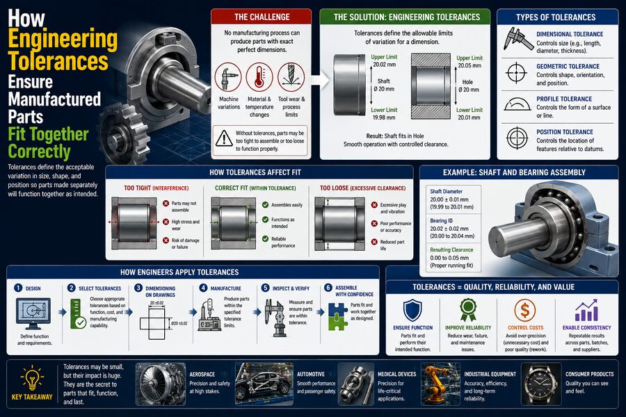

Manufactured products are built from parts that must interact with one another precisely. A shaft must fit inside a bearing. A bolt must pass through a hole. A piston must slide inside a cylinder. A gear must mesh correctly with another gear. A smartphone enclosure must close without gaps, while an aircraft component must align accurately enough to handle demanding loads.
At first glance, engineers might seem able to solve these problems simply by specifying exact dimensions.
For example:
Shaft diameter = 20.000 mm
Unfortunately, no manufacturing process can produce every part at exactly 20.000 mm. Cutting tools wear, machines vibrate, materials expand with temperature, measurements contain uncertainty, and manufacturing processes naturally produce small variations. ⚙️📐
Instead of demanding impossible perfection, engineers use tolerances.
A tolerance defines how much a manufactured dimension is allowed to vary while the part still performs correctly.
For example, a shaft might be specified as:
20.000 ± 0.010 mm
This means acceptable shafts can range from:
19.990 mm to 20.010 mm
By carefully selecting tolerances for mating components, engineers make sure separately manufactured parts can still assemble, move, seal, transmit force, and function reliably.
The key idea is simple:
Engineering tolerances allow controlled variation so real-world manufacturing can produce parts that still fit and work together correctly. 🔩✅
🧠 Why Exact Dimensions Are Impossible
Technical drawings often show dimensions to several decimal places, but physical manufacturing is never perfectly exact.
Suppose a CNC machine is programmed to manufacture 1,000 shafts with a diameter of exactly:
25.000 mm
When the shafts are measured, actual dimensions might be:
24.998 mm
25.003 mm
25.001 mm
24.996 mm
These differences may be extremely small, yet they are unavoidable.
Sources of variation include:
🔧 Cutting-tool wear
🌡️ Temperature changes
⚙️ Machine accuracy
📳 Vibration
🧱 Material variation
📐 Setup errors
📏 Measurement uncertainty
👷 Operator technique
Manufacturing engineering therefore does not attempt to eliminate all variation.
Instead, engineers decide how much variation the design can safely tolerate.
📐 What Is an Engineering Tolerance?
A tolerance defines the acceptable range for a dimension or geometric characteristic.
Suppose a drawing specifies:
50.00 ± 0.05 mm
The nominal dimension is:
50.00 mm
The upper limit is:
50.05 mm
The lower limit is:
49.95 mm
Therefore, the total tolerance is:
0.10 mm
Any part within that range is dimensionally acceptable for that particular requirement.
A part measuring:
50.03 mm
passes.
A part measuring:
50.08 mm
does not.
This simple range gives manufacturers room to work while still protecting the design function.
🎯 Nominal Size vs. Actual Size
The nominal size is the intended or reference dimension used in the design.
The actual size is what the manufactured part really measures.
For example:
Nominal shaft diameter: 10.000 mm
Actual shaft diameter: 9.994 mm
The part does not need to match the nominal dimension exactly.
It only needs to remain within its permitted limits.
This distinction is fundamental to manufacturing.
🔩 Why Fits Matter
When two parts interact, engineers often care about the relationship between their dimensions more than either dimension individually.
Consider a shaft going into a hole.
If the hole is always slightly larger than the shaft, the shaft can slide or rotate.
If the shaft is slightly larger than the hole, assembly may require force.
If their dimensions can overlap depending on manufacturing variation, some assemblies may be loose while others may be tight.
These different relationships are called fits.
Three important categories are:
- Clearance fit
- Transition fit
- Interference fit
↔️ Clearance Fit
A clearance fit ensures there is always space between mating parts.
For example:
Hole: 20.020 to 20.040 mm
Shaft: 19.980 to 20.000 mm
Even the largest possible shaft is smaller than the smallest possible hole.
Minimum clearance:
20.020 − 20.000 = 0.020 mm
Maximum clearance:
20.040 − 19.980 = 0.060 mm
This type of fit is useful when parts need to:
🔄 Rotate
↔️ Slide
🔧 Assemble easily
🛢️ Maintain lubrication space
Bearings, guide pins, and sliding components frequently use controlled clearance.
🔨 Interference Fit
An interference fit does the opposite.
The shaft is intentionally larger than the hole.
For example:
Hole: 49.980 to 50.000 mm
Shaft: 50.020 to 50.040 mm
The parts cannot normally slide together by hand.
Assembly may require:
🔨 Pressing
🔥 Heating the outer component
❄️ Cooling the inner component
Once assembled, the interference creates contact pressure.
This can prevent relative movement and allow components to transmit torque or load without additional fasteners.
Examples include:
⚙️ Gears pressed onto shafts
🔩 Bearing races
🚂 Railway wheels
🌀 Bushings
⚖️ Transition Fit
A transition fit lies between clearance and interference.
Depending on actual manufactured dimensions, the assembly might have:
- A small clearance
- Almost zero clearance
- A slight interference
Transition fits are useful where components must locate accurately but still remain reasonably practical to assemble.
They are often used for precise locating features.
🧮 Worst-Case Tolerance Analysis
Engineers must consider what happens when mating parts reach opposite extremes of their allowed tolerances.
Suppose:
Hole diameter = 10.00 ± 0.03 mm
and:
Shaft diameter = 9.95 ± 0.02 mm
The smallest possible hole is:
9.97 mm
The largest possible shaft is:
9.97 mm
Worst-case minimum clearance:
0.00 mm
The largest possible hole is:
10.03 mm
The smallest possible shaft is:
9.93 mm
Maximum clearance:
0.10 mm
The design therefore needs to work across an assembly clearance range from approximately zero to 0.10 mm.
This is known as worst-case tolerance analysis.
📚 Tolerance Stack-Up
Real products contain many dimensions connected together.
Small tolerances can accumulate.
This is called tolerance stack-up.
Imagine five components assembled in a row.
Each has a length tolerance of:
±0.10 mm
In the worst case, all five could be 0.10 mm too long.
Total variation:
5 × 0.10 = 0.50 mm
If the final assembly only has 0.20 mm of available space, components could interfere.
Tolerance stack-up analysis allows engineers to identify these risks before production begins. 📊
🏗️ A Door Assembly Example
Imagine engineers are designing a metal cabinet door.
The gap between the door and frame depends on:
- Frame width
- Hinge position
- Door width
- Hinge-hole location
- Sheet-metal bending accuracy
Each dimension may be individually acceptable.
Yet their combined variations could shift the door until it rubs against the frame.
By calculating the entire tolerance chain, engineers can ensure enough clearance remains even when several components are near their allowed limits.
This is why assembly problems cannot always be solved by looking at individual dimensions in isolation.
📊 Statistical Tolerance Analysis
Worst-case analysis assumes every dimension reaches its most unfavorable extreme simultaneously.
That provides strong assurance but can result in very tight and expensive tolerances.
In mass production, engineers may instead use statistical tolerance analysis.
Manufacturing dimensions often cluster around a target value rather than being uniformly distributed across the entire allowable range.
Statistical methods estimate the probability that several variations will combine unfavorably.
This may allow slightly wider individual tolerances while still maintaining a very low probability of assembly failure.
However, statistical tolerancing requires a stable and well-controlled manufacturing process.
💰 Tight Tolerances Cost More
It might seem safest to specify extremely tight tolerances everywhere.
For example:
±0.001 mm
But such precision can be expensive.
Tighter tolerances may require:
🛠️ More precise machine tools
⏱️ Slower machining
🔍 Additional inspections
🌡️ Temperature-controlled environments
🧪 Specialized manufacturing processes
♻️ More rejected parts
A dimension that could safely vary by ±0.1 mm should not normally be specified at ±0.001 mm just because greater precision sounds better.
Good engineering uses:
The widest tolerance that still guarantees required function.
This keeps manufacturing economical.
🎯 Functional Tolerancing
The best tolerance comes from understanding what the feature actually does.
Imagine a decorative cover panel.
Its hidden mounting hole might tolerate several tenths of a millimeter of variation.
Now consider the diameter of a hydraulic spool valve controlling precision fluid flow.
That dimension may require extremely tight control.
Both components may be part of the same machine, but their functional requirements are very different.
Engineering tolerances should reflect function rather than arbitrary precision.
📐 Size Is Not the Only Thing That Can Vary
Parts can have the correct dimensions and still fail to fit properly because their geometry is wrong.
For example, a shaft might have the correct diameter but be slightly bent.
A mounting surface may have the correct length and width but not be flat.
A hole might have the correct diameter but be located in the wrong position.
Therefore, engineers also specify geometric tolerances.
🧭 What Is GD&T?
Geometric Dimensioning and Tolerancing, commonly called GD&T, is a standardized system used to control geometric variation.
GD&T can specify characteristics such as:
📏 Straightness
⬜ Flatness
⭕ Circularity
🌀 Cylindricity
📍 Position
📐 Perpendicularity
↔️ Parallelism
🔄 Runout
🧩 Profile
This allows engineers to describe what really matters about a component’s shape and orientation.
📍 Position Tolerance Controls Hole Locations
Imagine a plate containing four bolt holes.
Each hole diameter may be correct, but if the holes are shifted too far from their intended locations, the bolts will not line up with the mating part.
A position tolerance defines a zone within which each hole’s axis must lie.
This is often much more useful than separately dimensioning horizontal and vertical coordinates with independent ± tolerances.
GD&T can represent assembly requirements more directly.
⬜ Flatness Matters for Sealing Surfaces
Suppose two machined surfaces must clamp together with a gasket.
Their length and width may be correct, but if either surface is badly warped, the gasket may not seal properly.
A flatness tolerance limits how far the actual surface can deviate from an ideal plane.
This is important for:
🛢️ Engine components
💧 Hydraulic systems
🧪 Process equipment
⚙️ Gearbox housings
Leak prevention may depend more on flatness than on the overall component size.
📐 Perpendicularity Helps Components Assemble Correctly
Consider a shaft mounted through a plate.
The hole axis should be perpendicular to the mounting surface.
If the hole is angled, the shaft may bind even when the diameter is correct.
A perpendicularity tolerance controls this angular relationship.
Geometric tolerances therefore ensure components not only have the correct size but also the correct shape and relationship to other features.
🎯 Datums Create Reference Systems
GD&T frequently uses datums.
A datum is a theoretically exact reference such as:
- A plane
- An axis
- A point
Manufacturers use datum features on the real part to establish a repeatable coordinate system.
For example:
Datum A: Bottom mounting surface
Datum B: Side face
Datum C: Locating hole
Other features are then measured relative to these references.
This helps manufacturers inspect parts in a way that matches how the component actually functions in an assembly.
🧩 Maximum Material Condition
GD&T includes concepts such as Maximum Material Condition, or MMC.
For an external shaft, maximum material condition means its largest allowed diameter.
For a hole, it means its smallest allowed diameter.
Why?
Because those conditions contain the greatest amount of material and often represent the most difficult assembly condition.
MMC can allow engineers to provide additional geometric tolerance when the actual component size creates extra clearance.
This is called bonus tolerance.
It can make parts easier to manufacture without sacrificing assembly function.
🔍 Inspection Determines Whether Parts Meet Tolerance
Once parts are manufactured, their critical characteristics must be measured.
Inspection equipment can include:
📏 Calipers
🎯 Micrometers
🧱 Height gauges
⭕ Bore gauges
📐 Surface plates
🧭 Coordinate Measuring Machines
🔦 Optical measuring systems
📡 Laser scanners
The appropriate instrument depends on tolerance magnitude and feature geometry.
A simple ruler cannot verify a ±0.01 mm diameter requirement reliably.
Measurement capability must be substantially better than the tolerance being inspected.
📏 Micrometers Measure Fine Dimensions
Micrometers are commonly used for precise external dimensions such as shaft diameters and material thickness.
A high-quality micrometer can resolve extremely small dimensional differences.
However, measurement results can still be influenced by:
🌡️ Temperature
🤲 Measurement force
🧹 Surface cleanliness
📐 Instrument alignment
Metrology is therefore its own engineering discipline.
🤖 Coordinate Measuring Machines Inspect Complex Geometry
A Coordinate Measuring Machine, or CMM, can measure the three-dimensional coordinates of points on a component.
From those measurements, software can evaluate:
- Hole positions
- Flatness
- Profiles
- Angles
- Datums
- Complex geometric tolerances
CMMs are widely used in automotive, aerospace, medical-device, and precision manufacturing.
They allow engineers to verify complex GD&T requirements that would be difficult to inspect with simple hand tools.
🌡️ Temperature Affects Precision Measurement
Materials expand when heated.
For ordinary construction, this may be insignificant.
For precision manufacturing, it can matter considerably.
A long metal component measured in a warm factory may have a slightly different size after cooling.
Precision metrology commonly references standardized temperature conditions, often around normal laboratory room temperature.
Manufacturers may use temperature-controlled inspection rooms when tolerances are extremely tight.
📊 Process Capability Connects Manufacturing to Tolerance
A drawing tolerance tells manufacturers what dimensions are acceptable.
But engineers also need to know whether the manufacturing process can consistently achieve them.
Statistical process-control metrics such as Cp and Cpk are used to evaluate process capability.
Conceptually, they compare:
Allowed specification width
with:
Actual manufacturing variation
A process producing parts very close to tolerance boundaries may technically make acceptable parts today but generate frequent defects as conditions shift.
A capable process operates with comfortable statistical margin.
🎯 Why Centering the Process Matters
Suppose an acceptable shaft range is:
9.95 to 10.05 mm
A manufacturing process has very little random variation but produces an average shaft diameter of:
10.045 mm
Most parts are close to the upper specification limit.
A tiny tool change could begin generating oversized shafts.
Engineers would prefer to center the process near:
10.00 mm
This maximizes room for normal variation.
Good manufacturing control therefore involves both:
📉 Reducing variation
and:
🎯 Keeping the process centered.
🛠️ Tool Wear Can Gradually Shift Dimensions
Imagine a cutting tool machining an outside diameter.
As the tool wears, the finished dimension may slowly change.
Manufacturers monitor this trend.
Instead of waiting until parts exceed tolerance, operators can compensate for tool wear or replace the tool proactively.
This is where tolerances, inspection, and statistical process control work together.
🔩 Interchangeability Made Mass Production Possible
Before modern manufacturing standards, many mechanical products were individually fitted by skilled craftspeople.
A replacement part might need hand filing before it would fit.
Controlled tolerances made interchangeable parts practical.
A bolt manufactured in one factory could fit a nut manufactured somewhere else, provided both complied with standardized dimensional requirements.
This was a major development in industrial production.
It enabled:
🏭 Assembly lines
🔧 Replacement parts
🚗 Large-scale automotive manufacturing
✈️ Aircraft maintenance
⚙️ Standardized machinery
Modern industry depends heavily on interchangeability.
🌍 Standards Help Manufacturers Agree on Fits
Engineering organizations publish standardized systems for dimensions, fits, and tolerances.
These help different companies design compatible components.
For shafts and holes, standardized fit systems can specify combinations designed to create predictable clearance or interference.
Using established standards reduces the need to invent a custom tolerance for every feature.
It also improves communication between designers and manufacturers around the world. 🌍📐
🔧 Tolerances Support Repairability
Imagine a pump shaft fails after ten years.
The manufacturer needs to produce a replacement.
If the original engineering drawings properly specify functional tolerances, a new shaft can be manufactured and installed without needing the original component as a physical reference.
This is essential for:
🏭 Industrial plants
✈️ Aircraft
🚢 Ships
🚗 Vehicles
⚡ Power equipment
Clear tolerances preserve the design definition throughout the product’s life.
🚗 Automotive Manufacturing Requires Huge Tolerance Coordination
A modern vehicle contains thousands of manufactured components.
Examples include:
⚙️ Engine parts
🔩 Transmission gears
🛞 Wheel bearings
🚪 Body panels
🔌 Electrical connectors
These components may be produced by hundreds of suppliers.
Each must meet defined dimensional requirements so final assembly occurs reliably.
If one supplier’s holes are consistently shifted by even a small amount, the resulting assembly problem can disrupt an entire production line.
Tolerance management is therefore a major part of automotive quality engineering.
✈️ Aerospace Tolerances Can Be Extremely Demanding
Aircraft components operate under demanding loads and reliability requirements.
Tolerance control can affect:
🌀 Turbine clearances
🔩 Fastener alignment
🪽 Aerodynamic surfaces
⚙️ Gear systems
💧 Hydraulic components
In a jet engine, for example, small clearances may strongly influence efficiency while excessive interference could cause rotating components to contact.
Aerospace manufacturing therefore combines detailed GD&T, high-precision machining, advanced inspection, and rigorous process control.
🩺 Medical Devices Also Depend on Precision
Medical components may contain extremely small features.
Examples include:
💉 Surgical instruments
🦿 Implants
🫀 Cardiovascular devices
🦷 Dental components
The required tolerance may affect fit inside the human body or interaction between miniature mechanisms.
Manufacturers must carefully control both dimensions and surface geometry.
🖨️ Additive Manufacturing Still Needs Tolerances
3D printing does not eliminate dimensional variation.
Printed parts can experience:
🌡️ Thermal distortion
📐 Layer inaccuracies
🧱 Material shrinkage
🔧 Surface roughness
Designers must understand the capability of the printing process.
A hole modeled at exactly 10 mm may not print at exactly 10 mm.
Tolerances therefore remain essential even in advanced additive manufacturing.
🧪 Prototype Tolerances May Differ From Production
During early prototyping, engineers may use manufacturing methods different from those intended for mass production.
For example:
Prototype: CNC machining
Production: injection molding
Each process has different dimensional capabilities.
Engineers should avoid assuming that tolerances achieved easily on a machined prototype will automatically be economical in molded production.
Design for manufacturing requires tolerance decisions that match the real production process.
🧴 Surface Finish Can Affect Fit Too
Dimensional tolerance is not the entire story.
Two shafts with identical measured diameters may behave differently if one has a rough surface and the other is polished.
Surface roughness influences:
🛢️ Lubrication
🔄 Friction
🔧 Wear
💧 Sealing
🔩 Press-fit behavior
Engineering drawings therefore often specify surface finish alongside dimensional and geometric tolerances.
🔄 Runout Matters for Rotating Components
A rotating shaft may have the correct diameter but wobble because its surface is not properly centered relative to its axis.
Runout controls this variation during rotation.
Excessive runout can cause:
📳 Vibration
🛢️ Seal wear
⚙️ Bearing problems
🔊 Noise
Rotating machinery such as motors, pumps, turbines, and machine-tool spindles relies heavily on runout control.
⚙️ Gear Manufacturing Requires Carefully Controlled Geometry
Gear teeth must interact with precise spacing and profiles.
If tooth geometry varies excessively, gears may experience:
🔊 Noise
📳 Vibration
🔥 Friction
⚙️ Uneven wear
Gear tolerances may control:
- Tooth thickness
- Pitch
- Runout
- Profile
- Lead
Accurate tolerancing helps maintain smooth torque transmission.
🔗 Assemblies Need Functional Clearance
Many moving assemblies require a small intentional gap.
Too much clearance can cause:
📳 Vibration
🔊 Noise
📉 Poor positional accuracy
Too little clearance can cause:
🔥 Friction
⚙️ Seizure
🛢️ Lubrication failure
The correct clearance is therefore a designed feature.
Tolerances must guarantee that the actual clearance remains within acceptable limits across all manufactured parts.
🌡️ Operating Temperature Can Change the Fit
A part may assemble correctly at room temperature but behave differently when hot.
Suppose an aluminum housing contains a steel shaft.
Aluminum expands more rapidly with temperature than steel.
As the assembly heats, the clearance can change.
Conversely, other material combinations may make an interference fit tighter or looser.
Engineers therefore consider not only manufacturing tolerances but also thermal expansion during operation.
💧 Lubrication Requires Space
Bearings, pistons, and sliding components often need a controlled gap for lubricating oil.
If the gap becomes too small:
🛢️ Oil may not flow properly
🔥 Friction may rise
⚙️ Components may seize
If the gap becomes too large:
📉 Pressure can fall
📳 Motion becomes unstable
💧 Leakage increases
Tolerance design therefore directly affects lubrication performance.
🧮 Geometric Tolerancing Can Sometimes Reduce Manufacturing Cost
At first, GD&T may appear more complicated than traditional ± dimensions.
But used correctly, it can make manufacturing less expensive.
Suppose a bolt hole has extra assembly clearance because its actual diameter is larger than its minimum allowed size.
GD&T with material-condition modifiers can permit additional positional variation in this situation.
Traditional coordinate tolerances might reject the same perfectly functional part.
This allows engineers to define acceptance based more closely on real assembly needs.
🧠 Tolerances Communicate Design Intent
A manufacturing drawing is a communication tool between engineering and production.
If engineers simply write:
Diameter = 20 mm
the manufacturer does not know how accurate it must be.
Should it be:
20 ± 1 mm?
20 ± 0.1 mm?
20 ± 0.001 mm?
Each requirement could demand a very different process and cost.
Tolerance communicates how important the dimension is.
It tells manufacturing:
This much variation is acceptable; beyond this point, function may be compromised.
🚫 Over-Tolerancing Creates Unnecessary Expense
A common design mistake is applying extremely tight tolerances to every dimension.
This may occur because designers believe precision automatically means quality.
But unnecessary precision can dramatically increase cost.
For example, a decorative cover plate does not need aerospace-grade machining if its only function is to hide internal components.
Over-tolerancing can lead to:
💰 Expensive machining
⏱️ Longer production times
🧪 Excessive inspection
♻️ Higher scrap rates
Good tolerance engineering focuses precision where it actually matters.
⚠️ Under-Tolerancing Creates Assembly Problems
The opposite mistake is allowing too much variation.
Loose tolerances may reduce part cost but cause:
🔩 Assembly failures
📳 Excessive play
💧 Leakage
⚙️ Misalignment
📉 Poor product performance
The cheapest individual component is not necessarily the cheapest overall product if it causes expensive assembly or warranty problems.
Tolerance selection must consider the entire product lifecycle.
🤝 Design and Manufacturing Engineers Must Work Together
A designer may specify a tolerance that appears reasonable on a drawing but is difficult for the chosen process.
Manufacturing engineers understand process capability.
Collaboration can identify better solutions.
For example, instead of demanding:
±0.005 mm
on a large cast surface, the team might redesign the interface so only a small machined locating feature requires high precision.
The result can preserve function while reducing cost.
This is an important principle of Design for Manufacturability, or DFM.
📊 Digital Tolerance Analysis Is Becoming More Advanced
Complex assemblies can contain hundreds of interacting dimensions.
Modern engineering software can build three-dimensional tolerance models.
These tools simulate manufacturing variation and predict:
📏 Assembly gaps
📐 Alignment errors
🔩 Interference risks
📊 Statistical failure rates
Engineers can identify problematic dimensions before tooling is manufactured.
This reduces the need for expensive physical trial-and-error.
🤖 Automated Inspection Is Expanding
Factories increasingly use automated inspection systems.
These may include:
📷 Machine vision
🔦 Laser scanners
🤖 Robotic measurement
🧭 Automated CMMs
📊 Real-time statistical monitoring
Measurements can feed directly into production systems.
If dimensions begin drifting toward tolerance limits, machine settings may be adjusted automatically.
This creates a closed-loop manufacturing process.
♻️ Good Tolerancing Reduces Waste
Appropriate tolerances can also improve sustainability.
Overly tight specifications create unnecessary rejected parts.
Every scrapped component represents wasted:
⚡ Energy
🪨 Material
⏱️ Machine time
🚚 Transportation
💰 Labor
By specifying only the precision necessary for function, engineers can reduce scrap while maintaining quality.
🔍 A Simple Example: Pin and Hole Assembly
Imagine a locating pin must enter a hole.
The pin diameter is:
10.00 ± 0.02 mm
So it can range from:
9.98 to 10.02 mm
The hole is:
10.08 ± 0.02 mm
So it can range from:
10.06 to 10.10 mm
Worst-case minimum clearance:
10.06 − 10.02 = 0.04 mm
Worst-case maximum clearance:
10.10 − 9.98 = 0.12 mm
The engineer now knows that every acceptable pin should fit into every acceptable hole with between 0.04 mm and 0.12 mm of diametrical clearance.
This is the essence of tolerance engineering:
Design the allowable variation so independently produced parts remain interchangeable.
🧩 Tolerances Are Part of System Engineering
Individual dimensions rarely exist in isolation.
A successful product requires coordinated control of:
📏 Size
📍 Position
⬜ Form
📐 Orientation
🔄 Movement
🌡️ Temperature effects
🧴 Surface finish
Together, these characteristics determine whether parts actually function after assembly.
Tolerance engineering is therefore not simply drawing annotation.
It is part of designing the complete mechanical system.
🚀 The Future of Tolerance Engineering
Modern manufacturing is moving toward more intelligent dimensional control.
Future systems increasingly combine:
🤖 Automated machining
📡 In-process sensors
🧠 AI-assisted quality monitoring
📊 Digital twins
🔦 High-speed 3D scanning
🏭 Smart factory systems
Instead of inspecting only finished parts, machines may continuously measure features and compensate for variation during manufacturing.
Even then, tolerances will remain essential.
Automation still needs to know:
What variation is acceptable?
That requirement comes from engineering design.
✅ Conclusion
Engineering tolerances make mass production possible by recognizing an unavoidable reality:
No manufactured part is perfectly identical to its design dimension.
Instead of demanding impossible precision, engineers define acceptable ranges within which parts will still perform correctly. 📏⚙️
For mating components such as shafts and holes, tolerances create predictable clearance, transition, or interference fits. Tolerance stack-up analysis ensures that small variations across many components do not combine into major assembly problems.
Geometric Dimensioning and Tolerancing expands this concept beyond simple size by controlling features such as position, flatness, perpendicularity, and runout.
Meanwhile, measurement systems and statistical process control verify that manufacturing remains capable of producing acceptable components consistently.
The most important principle is not to make every dimension as precise as possible.
It is to make each dimension precise enough for its function—and no tighter than necessary.
That balance creates products that are:
✅ Reliable
🔩 Interchangeable
💰 Economical to manufacture
🛠️ Easy to assemble
📈 Consistent at scale
From tiny medical devices to automobiles, aircraft engines, industrial machinery, and consumer electronics, engineering tolerances quietly determine whether independently manufactured components will fit together when they finally meet on the assembly line.
A difference of only a few hundredths of a millimeter may be invisible to the human eye, yet in precision engineering it can determine whether a machine runs smoothly—or whether its parts fit at all. 📐🔩✅