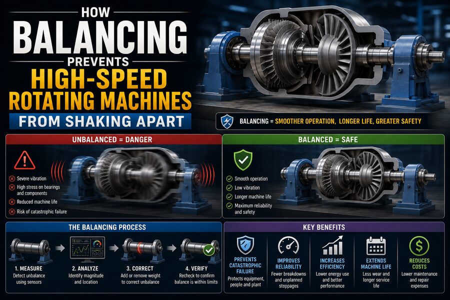

High-speed rotating machines are everywhere in modern engineering. Electric motors, turbines, compressors, pumps, fans, centrifuges, machine-tool spindles, automotive turbochargers, and generators may spin at thousands—or even tens of thousands—of revolutions per minute. 🚀
At those speeds, even a tiny uneven distribution of mass can create surprisingly large forces.
A rotor that is slightly heavier on one side may seem harmless while stationary. But once it spins rapidly, that extra mass continually pulls outward as it rotates. The direction of this force changes every revolution, producing a repeating load on bearings, shafts, housings, and foundations.
The result can be severe vibration.
If the imbalance is large enough, or if the machine operates close to one of its natural frequencies, vibration can become strong enough to damage bearings, crack components, loosen fasteners, wear seals, deform shafts, and eventually cause catastrophic failure. 💥
Balancing prevents this by adjusting the rotor’s mass distribution so that its center of mass and principal inertia axis align appropriately with its axis of rotation.
In simple terms:
A balanced rotor spins smoothly because its mass is distributed evenly around the axis.
🔄 What Is Rotating Imbalance?
Imagine a perfectly circular wheel mounted on a shaft.
If the wheel’s mass is distributed uniformly, its center of mass lies exactly on the rotational axis.
When the wheel spins, the centrifugal effects around the circumference cancel one another.
Now imagine attaching a small metal weight to one side of the wheel.
The center of mass shifts slightly away from the shaft.
As the wheel rotates, that heavier region constantly tries to move outward.
This creates a rotating force.
The machine experiences vibration at the same frequency as the rotor speed—often called 1× rotational frequency.
For example, if a shaft rotates at:
3,600 rpm
then:
3,600 / 60 = 60 revolutions per second
The imbalance force changes direction 60 times every second.
That can produce a strong vibration at approximately:
60 Hz
⚙️📈
🧮 Why Imbalance Force Becomes Huge at High Speed
The force produced by rotating imbalance increases approximately with the square of angular speed.
A simplified relationship is:
F = m e ω²
where:
F= centrifugal forcem= unbalanced masse= distance of that mass from the rotational axisω= angular speed
The important part is:
F ∝ ω²
If rotational speed doubles, imbalance force increases by approximately:
4 times
If speed triples:
9 times
If speed becomes ten times greater:
100 times
This explains why a tiny imbalance that is almost unnoticeable at low speed can become dangerous at high speed. 🚨
🧩 A Simple Example
Suppose a small 10-gram mass is effectively located 5 centimeters away from the rotational axis.
At low speed, it may generate only modest force.
But when the rotor spins at several thousand revolutions per minute, the outward force can become substantial.
That force repeatedly changes direction as the rotor rotates:
Right → Down → Left → Up → Right
The bearings and housing must resist this rotating load every revolution.
At 10,000 rpm, the direction changes more than:
166 times per second.
Even if each individual load cycle is small, millions of repeated cycles can create fatigue damage over time. 🔩
🏗️ Where Does Imbalance Come From?
No manufactured rotor is perfectly uniform.
Imbalance can result from:
- Manufacturing tolerances
- Uneven material density
- Casting imperfections
- Machining errors
- Keyways
- Welds
- Fasteners
- Uneven coatings
- Assembly errors
A rotor that was originally balanced can also become unbalanced during service.
Possible causes include:
- Material buildup
- Corrosion
- Blade erosion
- Wear
- Dirt accumulation
- Missing pieces
- Thermal distortion
- Repair work
For example, dust accumulating unevenly on an industrial fan can gradually create enough imbalance to produce noticeable vibration. 🌪️
⚖️ What Does Balancing Actually Do?
Balancing changes the distribution of mass around the rotor.
Engineers identify:
- How much imbalance exists.
- Where around the rotor it is located.
- At what axial position correction should be made.
They then either:
- Add mass
- Remove mass
- Shift existing mass
until the rotor’s imbalance falls within an acceptable tolerance.
Possible correction methods include:
- Adding balancing weights
- Drilling material away
- Grinding material
- Machining small areas
- Moving adjustable weights
- Adding screws or plugs
The goal is not necessarily perfect balance—absolute perfection is practically impossible.
Instead, the rotor is brought within an acceptable residual imbalance limit for its speed and application. 🎯
🔵 Static Imbalance
The simplest form is static imbalance.
Imagine a thin disk whose center of mass is offset from its shaft.
If the disk is placed on very low-friction supports, the heavy side may rotate downward under gravity.
This reveals the imbalance.
A correction mass can be added opposite the heavy spot—or material can be removed from the heavy side.
Static imbalance can often be corrected in a single plane.
This is common for relatively narrow rotors such as:
- Grinding wheels
- Small fans
- Pulleys
🔄 Couple Imbalance
Long rotors can have a more complicated problem called couple imbalance.
Imagine one end of a shaft is heavy on the top side, while the opposite end is heavy on the bottom side.
The overall center of mass might still lie close to the shaft axis.
A simple static test may not reveal a major problem.
But when the shaft rotates, the two unbalanced forces create a twisting or rocking moment.
This requires correction in at least two separate axial planes.
That leads to dynamic balancing.
⚙️ Dynamic Balancing
Dynamic balancing evaluates the rotor while it is rotating.
Sensors measure vibration or bearing forces.
The balancing machine determines both:
- Magnitude of imbalance
- Angular location of imbalance
For a long rotor, the system may calculate corrections in two planes.
Conceptually:
Plane A correction + Plane B correction → smoother rotation
Dynamic balancing is commonly used for:
- Electric motor rotors
- Turbine rotors
- Fans
- Pumps
- Crankshafts
- Compressors
- Generator rotors
🛠️
📡 How a Balancing Machine Detects Imbalance
A balancing machine supports the rotor and spins it at a controlled speed.
Sensors measure vibration or force generated by the rotor.
The system also needs a reference telling it the rotor’s angular position.
This may come from:
- Optical sensor
- Laser tachometer
- Magnetic pickup
- Encoder
The balancing computer compares vibration with rotational position.
It can then determine where the heavy spot is located.
For example, the machine might report:
Correction required: 4.2 grams at 215°
The technician can then make the specified adjustment.
📈 Vibration Has Magnitude and Phase
Balancing depends on more than simply measuring how much vibration exists.
Engineers also need the phase.
Magnitude tells:
How strong is the vibration?
Phase tells:
Where is the vibration relative to rotor position?
Suppose a machine vibrates strongly whenever a marked point on the shaft passes a certain angular location.
By comparing the vibration waveform with a once-per-revolution reference signal, diagnostic equipment can determine the angular location of the imbalance.
This allows precise correction. 🎯
🌀 Why Bearings Feel the Imbalance
Bearings support the rotating shaft.
When a rotor is unbalanced, the rotating centrifugal force is transmitted through the shaft into the bearings.
Instead of carrying mainly the intended radial and axial operating loads, the bearings experience an additional cyclic load.
This can cause:
- Higher bearing temperatures
- Increased noise
- Accelerated fatigue
- Lubricant degradation
- Premature bearing failure
Balancing therefore extends bearing life considerably in high-speed machinery. 🔧
🧱 Foundations Can Also Vibrate
The vibration does not stop at the bearings.
Forces can travel through:
Rotor → Shaft → Bearings → Housing → Machine frame → Foundation
A badly unbalanced machine may shake its entire mounting structure.
This can lead to:
- Loose anchor bolts
- Cracked foundations
- Pipe fatigue
- Electrical connection problems
- Misalignment
In large industrial facilities, vibration from one machine can even be transmitted into nearby structures and equipment.
🧨 Resonance Can Make Imbalance Much Worse
Every mechanical structure has natural frequencies.
If a periodic force acts close to one of those frequencies, the structure can experience resonance.
Imagine pushing a child on a swing.
If each push occurs at the right moment, the motion grows larger.
A rotating imbalance can do the same thing.
As rotor speed passes through a critical speed, the imbalance excitation frequency may approach a natural frequency of the rotor-bearing system.
Vibration amplitude can increase dramatically. 📈⚠️
This is why high-speed machinery must be designed not only for balance but also for safe behavior near critical speeds.
🚀 Critical Speeds
A critical speed is a rotational speed at which the rotor’s excitation frequency interacts strongly with a natural vibration mode.
Flexible rotors may pass through several critical speeds as they accelerate.
Large turbine and generator rotors can bend slightly while rotating.
Engineers analyze:
- Shaft stiffness
- Bearing stiffness
- Rotor mass distribution
- Damping
to predict these critical speeds.
Machines may be designed to:
- Operate below them
- Operate between them
- Pass through them quickly during startup
Proper balancing reduces the excitation force that drives resonance.
🏎️ Turbochargers Show Why Precision Matters
Automotive turbocharger rotors can operate at extremely high rotational speeds—often well above normal engine shaft speeds.
A turbocharger contains:
- Turbine wheel
- Shaft
- Compressor wheel
Because of the enormous speed, even a tiny imbalance can create major bearing loads.
Turbocharger assemblies therefore require extremely precise manufacturing and balancing.
A small amount of missing blade material or foreign deposit can significantly affect vibration. 🚗💨
✈️ Aircraft Engines Require Exceptional Balance
Aircraft turbine engines contain multiple rotating assemblies:
- Compressor stages
- Turbine stages
- Shafts
These components rotate at high speeds while operating under severe temperature and load conditions.
Rotor imbalance can create unacceptable vibration and fatigue.
Engine components are therefore carefully manufactured, balanced, assembled, and monitored.
Aircraft engines may also use vibration sensors to detect changes during service.
Increasing vibration can indicate:
- Blade damage
- Bearing problems
- Rotor imbalance
- Mechanical deterioration
✈️⚙️
⚡ Electric Motors and Generators
Electric machines also depend on rotor balance.
An electric motor rotor may spin continuously for thousands of hours.
Small imbalance can gradually damage:
- Bearings
- End shields
- Couplings
- Mounts
In large generators, rotor balance becomes even more important because the rotating mass can be enormous.
A small percentage of mass asymmetry can translate into very large forces.
High-quality balancing helps these machines operate smoothly and efficiently.
🌪️ Fans Are Especially Sensitive to Buildup
Industrial fans are common examples of machines that become unbalanced during service.
Airborne material may accumulate unevenly on blades.
Examples include:
- Dust
- Paint particles
- Process residue
- Moisture
- Ice
If one blade becomes heavier than the others, imbalance develops.
The fan begins vibrating.
Operators may detect rising vibration long before catastrophic failure.
Cleaning the rotor can sometimes restore balance without requiring a permanent correction weight.
🧼 Centrifuges Intentionally Spin Mass at High Speed
Centrifuges are particularly sensitive to load imbalance.
A laboratory centrifuge may spin sample tubes at thousands of revolutions per minute.
If samples are placed asymmetrically, the machine’s effective center of mass shifts away from the rotational axis.
The result can be violent vibration.
That is why centrifuge instructions often require tubes to be arranged symmetrically.
For example:
One sample tube → matching counterbalance opposite it
🧪⚖️
Large industrial centrifuges use the same basic physics, but with much greater forces.
🚗 Wheel Balancing Uses the Same Principle
Automotive wheel balancing is a familiar everyday example.
A tire and wheel assembly is never perfectly uniform.
Small weights are attached to the rim to correct mass imbalance.
Without balancing, the driver may feel vibration through:
- Steering wheel
- Seats
- Vehicle body
especially at particular road speeds.
The principle is identical to industrial rotor balancing:
Uneven rotating mass → periodic force → vibration
Correct the mass distribution, and the vibration decreases. 🚙
🧰 Field Balancing
It is not always practical to remove a large machine rotor and place it on a balancing machine.
Engineers can perform field balancing while the rotor remains installed.
Sensors are attached to the machine.
A reference vibration measurement is taken.
A known trial weight is added at a selected position.
The machine is run again.
By observing how the vibration changes, the balancing system calculates the required correction.
This is useful for:
- Large fans
- Blowers
- Pumps
- Industrial rotors
🏭
🎯 Trial Weights Help Reveal Rotor Response
A trial weight provides a known change.
Suppose the machine initially vibrates at:
6 mm/s
A known weight is added at 0°.
The vibration changes in both magnitude and phase.
Using these measurements, balancing software can calculate the rotor’s response to mass.
It then predicts the correction weight and angular location needed to reduce vibration.
This is known as an influence coefficient approach.
🔍 Balance Is Not the Only Cause of Vibration
A critical maintenance lesson is that not every vibration problem is caused by imbalance.
Similar symptoms can result from:
- Shaft misalignment
- Bent shafts
- Loose foundations
- Damaged bearings
- Mechanical looseness
- Gear defects
- Electrical problems
- Resonance
Imbalance often produces strong vibration at exactly 1× running speed, but diagnosis should consider the complete vibration spectrum and machine condition.
Simply adding balance weights to a misaligned or damaged machine may hide symptoms without solving the real problem. ⚠️
📊 Vibration Analysis Helps Diagnose Problems
Condition-monitoring systems use accelerometers and other sensors to measure machinery vibration.
A frequency spectrum breaks the vibration signal into components.
A strong peak at running speed may suggest imbalance.
Other frequency patterns may indicate:
- Bearing defects
- Gear mesh problems
- Misalignment
- Looseness
Vibration analysis therefore helps engineers decide whether balancing is actually needed.
Modern plants often continuously monitor critical machines to detect problems early. 📡
🧲 Balancing vs. Alignment
Balancing and alignment are different.
Balancing corrects uneven mass distribution in a rotating component.
Alignment ensures shafts and connected machines share the correct geometric relationship.
A perfectly balanced rotor can still vibrate if it is badly misaligned.
Likewise, perfectly aligned shafts can vibrate if one rotor is unbalanced.
Reliable machinery often requires both.
🧪 Balancing Standards and Quality Grades
Not every rotor needs the same level of balancing precision.
A slow industrial pulley may tolerate more residual imbalance than a high-speed precision spindle.
Engineering standards define balancing quality levels for different machine types.
The acceptable residual imbalance depends on factors such as:
- Rotor mass
- Operating speed
- Application
- Sensitivity of bearings and structure
Higher-speed equipment generally requires tighter balancing tolerances because imbalance force rises so rapidly with speed.
⚡ High-Speed Balancing
Some flexible rotors behave differently at operating speed than at low balancing-machine speed.
A long turbine rotor may slightly bend as rotational speed increases.
For these machines, high-speed balancing may be required.
The rotor is tested near relevant operating speeds in specialized facilities.
Engineers can then correct vibration associated with flexible rotor modes.
This is more sophisticated than ordinary low-speed rigid-rotor balancing.
🔥 Thermal Effects Can Change Balance
A rotor may be perfectly balanced when cold but develop vibration after heating.
Why?
Different parts of the rotor can expand differently.
Thermal gradients can slightly distort the shaft or move the effective center of mass.
This is called thermal bow or thermal imbalance in some situations.
Large turbines and generators are especially sensitive to thermal behavior.
Operators carefully control:
- Warm-up
- Cool-down
- Startup rates
to minimize distortion.
🧱 Why Balancing Extends Machine Life
Vibration creates cyclic stress.
Even when the stress is below the material’s immediate breaking strength, millions of repeated cycles can cause fatigue.
Cracks can begin at stress concentrations.
Over time, they grow.
Reducing vibration reduces these alternating stresses.
This helps extend the life of:
- Shafts
- Bearings
- Bolts
- Welds
- Housings
- Foundations
Balancing is therefore not merely about making a machine quieter—it is a fundamental reliability practice. 🛡️
🔇 Balancing Also Reduces Noise
Mechanical vibration often produces sound.
A shaking housing excites surrounding air.
Loose panels may rattle.
Bearings may generate additional noise.
By reducing the primary rotating force, balancing often makes machinery noticeably quieter.
This improves:
- Workplace comfort
- Equipment diagnostics
- Acoustic performance
Quiet operation can be a useful indirect sign that a rotating machine is running smoothly. 🔇
⚡ Energy Efficiency Can Improve
An unbalanced machine wastes energy by continuously shaking its bearings, housing, and foundation.
The additional mechanical motion creates losses.
Severe vibration can also increase bearing friction and component wear.
Balancing cannot eliminate all losses, but it helps ensure that more of the machine’s energy goes into its intended function rather than unwanted motion.
In continuously operated equipment, even small efficiency and maintenance improvements can have significant economic value. 💰
🧠 A Simple Analogy
Imagine holding a bucket by its handle and spinning it around.
If the weight is evenly distributed, the motion feels relatively predictable.
Now imagine a heavy object stuck to one side.
Every revolution produces a stronger tug in a particular direction.
The faster you spin, the harder the tug becomes.
A rotating machine experiences the same effect.
Balancing moves the effective mass distribution back toward the rotational axis so that these repeating forces cancel as much as possible.
🛠️ Preventive Maintenance and Balance Monitoring
Machines do not remain perfectly balanced forever.
Maintenance programs may track vibration trends over time.
Suppose a fan’s vibration gradually changes:
Month 1:
2.0 mm/s
Month 3:
2.8 mm/s
Month 6:
4.6 mm/s
Month 8:
7.1 mm/s
The trend may indicate worsening imbalance or another developing fault.
Maintenance teams can investigate before the machine reaches a dangerous condition.
This is a core idea in predictive maintenance. 📈🔧
💥 What Happens If Imbalance Is Ignored?
Severe imbalance can trigger a chain of failures.
First:
Vibration increases.
Then:
Bearing loads rise.
Next:
Bearing clearances and temperatures worsen.
Then:
Shaft motion increases.
Eventually:
Seals, couplings, fasteners, or structural components may fail.
In extreme cases, rotating parts can contact stationary housings or break apart.
At very high speed, fragments contain enormous kinetic energy.
This is why critical rotating machinery often includes vibration alarms and automatic shutdown systems. 🚨
🛑 Vibration Trip Systems
Large turbines, compressors, and generators may have sensors permanently installed near their bearings.
These systems continuously measure parameters such as:
- Shaft displacement
- Bearing housing vibration
- Rotor position
If vibration exceeds an alarm threshold, operators are warned.
If it reaches a dangerous trip threshold, the protection system can shut the machine down automatically.
This provides a final line of defense if imbalance or another fault begins to threaten mechanical integrity.
✅ Conclusion
Balancing prevents high-speed rotating machines from shaking apart by reducing the uneven centrifugal forces created when a rotor’s mass is not distributed correctly around its axis. ⚙️🛡️
Even a tiny imbalance can become dangerous because centrifugal force increases approximately with the square of rotational speed. A harmless-looking mass error at 500 rpm can become a serious source of vibration at 10,000 rpm.
Balancing equipment measures the magnitude and phase of this vibration and determines where mass should be added, removed, or repositioned.
Thin rotors may require only single-plane correction, while long rotors often require dynamic two-plane balancing to eliminate both static and couple imbalance.
Proper balancing reduces cyclic loading on bearings, shafts, housings, seals, foundations, and connected equipment. It also reduces noise, improves reliability, extends fatigue life, and helps prevent resonance from amplifying vibration near critical speeds.
From automobile wheels and laboratory centrifuges to jet-engine rotors, power generators, industrial fans, and turbochargers, the same principle applies:
Keep the rotating mass centered on the rotational axis, and the machine can spin smoothly instead of fighting itself every revolution. 🔄
At high speed, balance is not simply a matter of comfort or refinement. It is one of the fundamental requirements that allows powerful rotating machinery to operate safely for thousands of hours without destroying its own bearings and structure. 🚀⚙️