14.1 STARTUP
Any plant operation can be divided into three types of operating steps, namely, startup, production, and shutdown. Startup and shutdown operations are unsteady state and unproductive operations. Usually, production operation is carried out for 330 days a year and 35 days are left for repair and maintenance of the plant and equipment; during this period no production is carried out. After shutdown, the startup operation is carried out until continuous production is achieved. Thus, downtime between shutdown and startup operations should not exceed 35 days. Of course, these time limits vary from plant to plant. Rarely, the partial shutdown and startup operation of a plant unit may be carried out without affecting other units such that the production from the rest of the plant may continue throughout the year. At the beginning, the power plant must be started up to supply power and steam to the plant. When the power and utilities are available in full swing, next the processing plants are started up in a sequence. For example, in a refi nery, the crude distillation plant is started fi rst. When the products from this plant meet the desired specifi cations (on spec), the secondary plants, e.g., the naphtha pretreatment and reforming plants, are started up. In fact, for old plants where suffi cient storage of intermediate products is available, all the secondary plants are started up simultaneously along with the crude distillation unit. Startup of every process plant is unique, depending on the design and operating conditions of the equipment in that plant. Though it is not possible to discuss startup procedures for every plant in a refi nery or a petrochemical plant, some of the common steps will be discussed here.
14.1.1 POWER PLANT STARTUP
As described earlier, in a power generation plant, boiler feed water (BFW) is heated up and converted to steam to drive the turbine-alternator to generate electricity. The boiler startup is a crucial step carried out by a team of experts. Initially, pumps, blowers, compressors and other rotary machines are started after acquiring the necessary power from power plants of other companies or organisations. The instrument air supply compressors are started, the instruments are checked before putting them online. Feed water is allowed to fl ow in the furnace coils of the economiser, boiler, and superheater, and circulation is established. Next, the water level in the boiler drum is monitored and controlled. Cooling water fl ow is established through the condenser. The draft fans are started next to ensure the desired draught in the fl ue gas circuit from the superheater, boiler, economiser, and then to the stack, in this order. Fuel gas lines are opened through the pilot burners of the furnace and lit up with automatic sparking. The temperature of water in the boiler rises gradually to its saturation temperature after some time. As the steam attains at its required pressure and temperature, steam valves to the turbine are opened and condensates are collected through the condenser circuit. The alternator poles are supplied with a DC power through a DC converter from the external power supply or through a battery of storage cells. Steam pressure and level of water in the boiler drum are controlled with the help of automatic controllers until a steady production of desired steam quality is generated. After establishing the desired speed of rotation of the turbine, power generation is observed for steady supply. When suffi cient steam pressure is available, the atomising of liquid fuel is started in the furnace burners and fuel gas to the pilot burners is withdrawn so that the furnace is run with a steady supply of furnace oil or internal fuel oil (IFO) from storage. As the power is generated in full swing, the external power supply along with the dc supply from battery to alternator poles is withdrawn. Note that, during this production period, the alternator is synchronised with a dc generator set to supply necessary dc power for the poles while the turbine rotates and drives both the alternator and the dc generator simultaneously while power generation is peaked up by the alternator.
14.1.2 STARTUP OF A CRUDE DISTILLATION UNIT
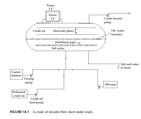
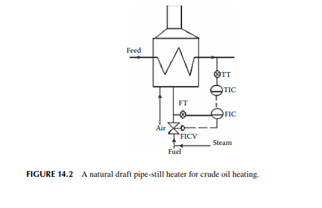
After the supply of power and utilities are ensured, the crude distillation unit is started. Initially, steam lines are opened to maintain the necessary temperature of the steam-traced lines for the pipes, pumps, and equipment, wherever steam-tracing lines are provided. Care must be taken to check that the condensate draws through the steam chest containing the condensate drain valves. It should be noted that if steam leaks without condensing through the condensate release valves (fl oat valves), heat equivalent to the latent heat of the steam leaked will be lost. Establishing this steaming rate will take some time as the lines will be cold initially. Certain pumps are operated at different temperatures, i.e., a crude feed pump is a cold pump while the booster pump drawing desalted crude from the desalter is a hot pump. Certain pumps are operated by steam turbines, therefore it is essential to check the steam pressure and its fl ow through the condensate drain points while the steam inlet valves are kept closed, otherwise these pumps will start running suddenly and will upset the plant. Hence, it is essential to check the valves (manually operated) as some of these must be fully open and others must be shut as per the processing requirements. The startup lines must be checked for any leakage, damage, undesirable openings, etc. Cooling water through the condensers and coolers must be opened through their respective valves (mainly manually operated). Steam purging is carried out through the process lines and startup lines, if any, before any hydrocarbon liquid is introduced. Crude is allowed to fi ll the desalter by gravity through the crude discharge line of the feed pump and a suffi cient level is built up. Water draining from the desalter drum and other points is carried out. The crude pump is then started after ensuring suction from the storage tank to the heat exchanger trains, desalter drum, furnace, and the distillation column. Since crude is cold and the hot fl uid streams in the heat exchanger trains are unavailable, no vaporisation will start in the column. However, the column is fi lled with propane or butane or liquifi ed petroleum gas (LPG) from a storage bullet to maintain the pressure within the column in order to avoid any ingress of air from the atmosphere. Thus, liquid crude will accumulate at the bottom of the column from where it will be pumped out under level control, back to the suction of the feed pump and cold circulation will be established. The furnace is then lit with the pilot burners and a gradual temperature rise is observed. As the coil outlet temperature (COT) of the furnace rises, care must be taken to avoid vapour locking of the bottom draw (reduced crude oil (RCO)) pump as the crude at the bottom of the column starts vaporising. Usually, as the COT of the furnace reaches 200°C, the rate of heating should be increased quickly to raise the temperature above this, which will ultimately help vaporise the crude oil to the maximum extent and make the bottom product free from vaporisable components. Hot bottom products return through the crude preheaters and the water cooler before they move to the feed pump suction. This explains why a cold feed pump can tolerate RCO during startup, which was hot while drawn from the column, but suffi ciently cooled before reaching the feed pump, thereby avoiding vapour locking of the feed pump. But this will be stopped as soon as the products from the column are withdrawn and routed to their respective slop tanks. During this circulation, as the temperature from the preheaters reaches 95°C, the desalter transformer is switched on after establishing water and caustic injections. The bottom draw is gradually routed to the RCO tank with complete cut off from the suction. If the furnace reaches a high temperature, but the crude fl ow is below the minimum fl ow rate, the RCO pump will recirculate RCO through the furnace coil to avoid coking, which may otherwise lead to devastation if the coils are choked with coke. As the furnace temperature rises, vaporisation of crude occurs in the column and the temperature and pressure of the top condensate level over the refl ux drum are monitored and controlled. While a suffi cient level is built up in the refl ux drum, the top refl ux pump is started, followed by starting of the circulating refl ux pumps, taking the utmost care to avoid vapour locking due to drying of the draw plates. Next, the top product is partially drawn along with the draws of kerosene, diesel, and jute batching oil through the strippers in sequence. These products are sampled for analysis and routed through their respective intermediate slop tanks until these are certifi ed as on spec products. Later, slops are reprocessed with crude when there is an accumulation of suffi cient slops or when there is a shortage of crude stock in future. Of course, the startup procedure is successfully carried out only by a team of experts, novices are advised to follow the instruction manuals. Proper planning is essential to prepare fl ow paths, such as leak testing, steam purging, blinding/deblinding operations, crude fi lling and circulation, furnace light up, desalter startup, slop and product routine, etc.
14.1.3 STARTING A NAPHTHA PRETREATMENT PLANT
After ensuring power, steam fl ow, cooling water fl ow, and warming up of the steamtraced lines, the feed pump is started. Utmost care is taken during leak testing of the process lines and equipment by compressed air pressure, followed by repeated vacuum and purging with nitrogen. Cold feed from the storage is pumped directly to the stabiliser column through a separate startup line, bypassing the train of heat exchangers, the furnace and the vapour liquid separator (fl ash drum), and the reactor. As a suffi cient liquid level is accumulated in the bottom of the column, bottom liquid is recirculated. The reboiled naphtha is then pumped to the feed pump after being suffi ciently cooled by the aftercooler. The stabiliser column is suffi ciently pressurised with fuel gas and refl ux condenser is started. There will be no vapour as the furnace is not lit and the liquid accumulated at the bottom of the stabiliser is returned to the feed pump and cold circulation (low pressure circulation section) is established. Hydrogen from storage is used up to pressurise the V–L separator drum by forcing hydrogen through the feed preheaters, the furnace, and the reactor, and the hydrogen is circulated back to the recycle compressor suction, establishing high pressure circulation. Next, the furnace is lit up and hot hydrogen is circulated through the reactor. The catalyst is also sulfi ded during this circulation for a specifi ed time at a desired temperature. As the reactor reaches reaction temperature, feed is introduced along with hydrogen through the preheaters, the furnace, and the reactor and, fi nally, to the V–L separator. When a suffi cient level is built up in the separator drum, it is routed to the stabiliser column and the circulation through the startup line is stopped. Finally, the bottom product is routed to the slop tank until the bottom product is tested for the extent of desulfurisation. In fact, if a suffi cient quantity of hydrogen is not available during startup, it is advisable to startup the reforming unit prior to the pretreatment unit provided that a suffi cient stock of desulfurised naphtha is available. 14.1.4 STARTING A NAPHTHA REFORMING PLANT Startup of a naphtha reforming plant is similar to the startup procedure of a pretreatment unit. Feed is introduced to the debutaniser and circulated through a startup line, bypassing the reactor section (high pressure section) consisting of the preheaters, furnaces, reactors, and the V–L separator. Hydrogen is circulated in the reactor section and the furnaces are lit up. Necessary catalyst additives are also injected during the hot circulation for a specifi ed period. As the temperature of the reactors rises to 470°C, the reaction temperature, feed is switched to the high pressure section along with recirculating hydrogen. As the level in the bottom of the separator drum is built up, the liquid from the separator drum is routed to the debutaniser column and the fl ow through the startup line is stopped.
14.1.5 STARTING A FLUID CATALYTIC CRACKING PLANT
A fl uidised bed catalytic cracking plant (FCC) may be divided into three units, i.e., the reactor (converter), the regenerator, and the distillation unit. These three units must be positively separated by blinding from each other. After ensuring the supply of power and utilities, the air fl ow is established in the regenerator while the fl ue gas lines to the waste heat boiler must be kept closed. Air is blown out to the atmosphere. After draining the water and suffi cient air pressure development and leak testing are carried out, the performance of the control valves are checked. The catalyst is loaded and fl uidised in the regenerator vessel. When a suffi cient level is built up, the reactor side is opened to allow the catalyst to fl ow to the riser and back to the regenerator. During fl uidisation with air and catalyst circulation, air in the reactor is blown out to the atmosphere. A suffi cient level of catalyst is built up in the stripper section of the converter and a steady catalyst circulation is maintained. The slide valves and controllers are checked for the overridding control action for temperature performance for temperature and differential
pressure drop over the control valves. Steam is then introduced in the reactor riser, the stripper, and at the upstream of the slide valve of the spent catalyst, stand pipe and downstream of the slide valve of the regenerated catalyst fl ow lines. Fluidisation of the catalyst with steam is established. The waste heat boiler is commissioned with a water fl ow rate under level control. The distillation column is pressurised with fl ue gas and cold circulation is established with feed hydrocarbon so that as soon as the products are generated from the reactor, the distillation unit will process them. The startup procedures for the distillation unit and the crude distillation unit are the same. When steam purges out air from the reactor through the vent to the atmosphere, preheated feed hydrocarbon is introduced to the riser and the steaming rate is further adjusted to maintain fl uidisation and catalyst circulation. Cracked products (after deblinding the feed to the distillation unit) are routed to the distillation unit under cold circulation. As the reactor temperature is established, the cold circulation is stopped and products from the distillation column are routed to their respective slop tanks until these meet the specifi cations. Flue gases from the regenerator are then routed to the waste heat boiler. Details of the startup procedure for the FCC unit are lengthy and a discussion of it is out of the scope of this book. Readers are advised to follow the instruction manual and emphasise the specifi c points of safety, such as positive isolation of hydrocarbons from air, sequences of the blinding/deblinding schedules, gradual rise of temperature in steps (ramping of temperature rise), taking care of the refractory linings, differential pressure drops over the slide valves, maintaining freeness in the distributors for air and steam, respectively, in the regenerator and the reactor, etc.
14.2 SHUTDOWN
As already mentioned in the foregoing section, a plant is down for about 30–35 days a year for necessary repair and maintenance jobs. Various jobs are performed, such as
1. Cleaning of equipment, e.g., heat exchangers, furnaces, columns, vessels, etc.
2. Repair of pipes, equipment joints, supports, etc.
3. Painting of external surfaces of pipelines and equipment for protection from oxide corrosion
4. Painting of internal surfaces of certain vessels, relaying protective lining inside certain equipment, e.g., column, furnace etc.
5. Repair and testing of pumps, compressors, and other machines
6. Checking of controlling instruments, sensors, control valves, instrument air lines, signal cables, etc.
7. Catalyst regeneration and loading for fi xed bed reactors
8. Fixing column plates and valves, distributors, etc.
9. Steam pipes, steam valves, condensate drain valves, steam-traced lines, etc.
10. Checking electrical meters, e.g., ammeters, voltmeters, power meters, integrators, switches, fuses, tripping devices, motor control centres (MCC), etc.
11. Checking transformers, electrical supply cables, fl ame proof arrangements, etc.
12. Modifi cations and alteration of existing plant and equipment Shutdown of a running plant is a procedure opposite to that followed during startup
14.2.1 SHUTDOWN OF A CRUDE DISTILLATION UNIT The fi rst step is to reduce the crude throughput in the unit by gradually reducing the set point. As the fl ow rate comes down, the fuel consumption automatically comes down in the furnace. The pumps for circulating refl ux, overhead, and draws are stopped when the levels over the respective draw plates have fallen. As the throughput comes to a minimum fl ow, the products are routed to their respective slop tanks and gases to fl are. The temperature controller is put on manual and the fuel valves are closed. After the burners are switched off, steam is used to purge off the furnace chamber. The RCO is circulated to the furnace coils along with crude, while the crude fl ow is further cut and a steady circulation of the RCO is established in the furnace. As the temperature of the furnace comes down, the RCO is routed to the RCO tank until the column bottom is nearly empty. The positive pressure is maintained by keeping the vapours in the column and steam is simultaneously introduced into the column. It is to be remembered that none of the equipment or process lines are open to the atmosphere nor is any ingress of air allowed by maintaining a positive pressure either by the hydrocarbon vapours or by steam. After suffi cient cooling of the lines and equipment, steaming is replaced by nitrogen and is allowed to cool to room temperature. The feed pump connections, slop lines, product lines, fuel and fl are lines, etc., are blinded. The equipment and lines are then opened and the necessary cleaning and repair jobs are carried out.
14.2.2 SHUTDOWN OF A NAPHTHA PRETREATMENT UNIT
The naphtha feed rate is gradually reduced and when it reaches minimum, the furnace temperature is reduced and the product naphtha is routed to a raw naphtha tank. The fl ash drum bottom valve is isolated and the bottom of the stabiliser is recirculated to the feed pump via the cooler and low pressure side circulation is established. While hydrogen circulation is continued through the feed preheaters, the furnace, the reactor, and the fl ash drum, hot circulation (high pressure side) is continued until all the hydrocarbons are swept from the reactor bed and purged through the fl are line. When the level in the stabiliser bottom is nearly empty, the column is bottled up, keeping some positive pressure. After suffi cient sweeping of the catalyst bed is achieved by confi rming the sample of recycled gas, the furnace is switched off. The hydrogen circulation is continued to cool the reactor bed and later the compressors are stopped. A positive pressure is maintained in the circulation line. Next, the catalyst is regenerated in situ in the bed, which is discussed in the following section.
14.2.3 REGENERATION OF THE CATALYST
The steam ejector is started to draw is next connected to draw the contents and vacuum is drawn followed by the introduction of steam to break the vacuum. The process is repeated until all the hydrocarbons in the high pressure section are removed. The furnace is lit up and air along with steam is introduced in the reactor section. At a temperature above 200°C, combustion is initiated with the coke and air over the catalyst. The rise in temperature due to combustion is monitored and controlled
by manipulating the air rate. The fl ue gas is exhausted to the atmosphere. The temperature of the reactor bed is sensed by a number of thermocouples to track the uniformity of the temperature over the catalyst surface. A sudden increase in temperature over a desired limit will indicate hot spots, which may damage the catalyst and immediate air fl ow reduction must be maintained. The temperature profi le over the bed height is recorded during the regeneration process and compared with that specifi ed by the catalyst vendor. Steaming also helps to dislodge the coke and hydrocarbons, if any, over the catalyst surface. It is noted that the catalyst is not affected by steam.
14.2.4 SHUTDOWN OF A NAPHTHA REFORMING UNIT
Decommissioning of a naphtha reforming unit is similar to that followed in the pretreatment unit. The throughput to the unit is fi rst reduced gradually to the minimum rate and then the furnace temperature is gradually reduced. Product reformate from the debutaniser is routed to the naphtha tank and later circulated back to the feed pump through a narrower startup line. Thus, low pressure side cold circulation is established. A low liquid level at the bottom of the fl ash drum is maintained and the discharge to the debutaniser is closed. Hydrogen is circulated through the preheaters, furnaces, reactors, and fl ash drum and returned to the recycle compressor. Thus, high pressure section circulation with hydrogen is established. Hot circulation is continued for some time to remove any hydrocarbon remaining in the reactor beds and lines. The hydrogen along with the hydrocarbon gases and vapours are sent to the fl are, bypassing the fuel gas and hydrogen consumption units. When the purged gas sample shows minimum hydrocarbon vapours, the furnaces’ temperature is reduced and fi nally fuel injection is stopped. Hydrogen is then replaced by nitrogen and circulated through the high-pressure side and released to fl are, while the debutaniser level is reduced to minimum and the fuel gas line is replaced by nitrogen to keep some positive pressure within the column. The cold circulation is stopped and the bottom of the debutaniser column is gradually dried out by draining to the naphtha tank. When the reactor temperatures reach room temperature, the compressors are stopped, and regeneration of catalyst is started.
14.2.5 REGENERATION OF REFORMING CATALYST
A reforming unit uses platinum as the catalyst with or without a promoter like rhenium (for bimetallic catalyst) in a fi xed bed reactor. During reforming reactions, coke formation cannot be avoided, although at a reduced rate in the presence of hydrogen pressure. Coke deposited on the surface of the catalyst causes temporary deactivation of the catalyst and, as a result, the catalytic action ceases to produce the desired quality of reformate. If coke is burnt by oxidation to free the catalyst surface, catalytic activity is regained to the maximum extent and can be reused. The unit is decommissioned as described in the earlier section, followed by drawing vacuum with a steam ejector to evacuate any residual hydrocarbons in the reactor section, consisting of the preheater, furnaces, reactors, and the fl ash drum. The reactor section is isolated from the debutaniser column before vacuum is drawn. Nitrogen (not
steam, as it will poison the catalyst) is introduced through the recycle compressor discharge line to break the vacuum. This process of drawing vacuum and fi lling with nitrogen is repeated until the oxygen content is negligibly small. The furnaces are then lit up to raise the temperature of nitrogen to around 200°C and air is introduced with caution so that combustion in the reactor bed is started slowly. The temperature of the entire bed is monitored by a number of thermocouples inserted at various locations within the catalyst bed. As the temperature at any spot increases suddenly above a certain specifi ed limit, overheating or a hot spot is located and immediately the air fl ow rate is reduced. A plot of temperature against time during the regeneration period is recorded continuously to ascertain the uniformity of regeneration. The fl ue gas with nitrogen is continuously ejected to the atmosphere. As the temperature of the catalyst bed does not rise above the furnace temperature, the end of combustion is ensured. (At this stage, oxychlorination of the catalyst is also carried out for the necessary isomerising function of the catalyst. A halogen source, usually carbon tetra chloride, along with air is introduced at the desired reaction temperature). Next, the furnace temperatures are reduced and fi nally the fuel injection is cut off while nitrogen circulation is continued until the temperature reduces to room temperature. The compressors are then stopped and isolated from the unit and the equipment is opened for cleaning and repair jobs. Reloading of a fresh catalyst is also carried out in the reactors.
14.3 MAINTENANCE OF PLANT AND EQUIPMENTS
The maintenance jobs of a plant involves a team consisting of various engineering and technical experts from fi elds, such as mechanical, electrical, civil, metallurgical, instrumentation, computer, electronics, etc. The repair and maintenance jobs of machines against their mechanical failures may be carried out in three ways.
1. During the annual shutdown period: Repair and maintenance of equipment and machines, which cannot be isolated from the process without affecting production, are carried out. However, if the plant is integrated in such a way that each unit can be run independently for a certain period without affecting the other units in the plant, partial shutdown can be done at any time.
2. Periodically carried out throughout the year: Usually, the running hours of the pumps, compressors, and other machines are continuously recorded in any plant. After certain running hours, these machines must be checked and the necessary rectifi cations made. In fact, while these machines are removed from service, spare machines must be taken in line to maintain production. In other words, machines that have at least another duplicate machine (spare machine) in operation can only be repaired periodically. This type of maintenance is essential for any plant to prevent an accident during production. Hence, this is also known as preventive maintenance.
3. At the time of failure or accident: In case of sudden damage to any machine during the running period, it is inevitable to run the spare machine and the failed machine must be repaired. In fact, this type of repair and maintenance is unwanted in any plant, but unfortunately these failures are either due to lack of supervision and operating skill or improper repair during annual or periodic maintenance. These types of failures may even lead to an accident small or big and cause huge loss to the organization. Maintenance of instruments is similarly carried out for all sensory elements, cables, fi lters, controllers, control valves, and control panels. Periodic tuning of the controllers is also carried out. For a DCS control system, the control software must be checked for performance and reproducibility. A necessary update is also essential for any change in the plant due to the addition or modifi cation of the plant and equipment. An inspection must be carried out on the security instruments, e.g., safety valves, safety switches, fuses, trippers, alarms, etc. Civil maintenance looks after the repair of underground or overground bridges, culverts for pipe racks, pits, roads and approaches for the movement of light and heavy vehicles, for the removal and positioning of machines and equipment, painting and lining jobs, addition or modifi cation of buildings, etc. The inspection of materials of construction, testing piping and structures, inspection of column shells, vessel walls, etc., is carried out by a group of experts from metallurgical engineering. Common, sophisticated methods, such as ultrasonic and x-ray, are used for testing the plate thickness of vessels. Chemical composition analysis may also be required to determine the quality of the steel and other building materials. Correlations of composition and thickness may predict the permissible limits of the operating load, temperature, corrosion, and life of the materials. Inspections are carried out annually during shutdown, periodically, and also at the time of failure.
14.4 FIRE AND EXPLOSION
Fire is the result of an exothermic reaction between combustible matter and oxygen (from air) at a certain temperature. Fire, big or small, may be caused by oxidation of hydrocarbons (combustibles) ignited by a small spark or heat. The cause of fi re may be small, but it can lead to a small or large fi re and may be associated with explosion. Hydrocarbons are classifi ed as most dangerous, dangerous, and non-dangerous goods as per explosive rules. Liquid hydrocarbons are also classifi ed according to their increasing fl ash points as class A, B, and C. Class A products are highly infl ammable and have fl ash points below 23°C, e.g., crude oil, naphtha, motor spirit, viscositybroken-gasoline, pyrolysis-gasoline, benzene, toluene, xylene, etc. Class B products are also infl ammable, but less volatile than class A products. Class B products have fl ash points greater than 23°C but less than 65°C, e.g., kerosene, aviation turbine fuel, mineral turpentine oil, high speed and light diesel oils, furfural, etc. Class C products are almost non-volatile at atmospheric pressure but can be vaporised under vacuum. These products have fl ash points greater than 65°C but below 95°C. Examples of class C products are jute batching oils, RCO, vacuum distillates, short residues, asphalts, furnace oil, etc. It is found that a minimum temperature required for ignition of the combustible matters must be attained for the production of fi re even in the absence of any spark or fl ame. This temperature is known as the auto ignition
temperature, which is a property of infl ammable substances, whether solid, liquid, or gas. For example, a typical gasoline (class A product) has an auto ignition temperature of 246°C, whereas the auto ignition temperatures of a typical kerosene (class B product) and bitumen (class C product) are, respectively, 254°C and 485°C. Besides auto ignition temperatures, the relative concentration of the combustibles and air necessary for the combustion or explosion are known as the limits of explosion or infl ammability. The concentration of air is known as the lower limit of explosion and if it is much lower than that of the combustibles, incomplete combustion occurs. If air is present in large amounts with respect to the combustibles, and complete combustion occurs, this concentration of air is known as the upper limit. Hydrocarbons become explosive when the air concentration falls above or below the limits of infl ammability. During incomplete combustion, gas expands in volume followed by a quick reduction in volume owing to the cooling effect of the expansion of the unconverted combustible gas or liquid. Such a sudden expansion followed by compression can cause knock or explosion. Whereas during complete combustion, the heat generated is huge and can cause a sudden expansion of the combusted gas mixture, leading to explosion in a closed container. If suffi cient space is available, a continuous fi re will take place without explosion. Thus, fi re and explosion are dependent on the fl ash point (which means ease of vaporisation), auto ignition temperature (reaction temperature for combustion), the presence of oxygen (usually from air), and the space occupied during such a reaction. The degree of explosion depends on the heat of the reaction (heating value) of the combustibles and the volume of the container. The extent of fi re (duration) is also dependent on the amount of combustibles present while suffi cient oxygen is available. The mechanism and pathways of combustion reactions are rather complicated by the nature of the combustible matters involved, coupled with the heat and mass transfer phenomena of the oxygen and product of combustion. Thus, fi re can be doused by any or combined means as
1. Cooling by water, to quench the heat of reaction.
2. Blanketing air by water spray or steam or inert gas or foam or sand (for a small fi re) to starve the reaction of oxygen.
3. Spaying of oxygen-absorbing chemicals.
4. Reducing the supply of combustibles by quickly cutting off the remaining amount by pumping it out of the equipment or vessel, if possible. The causes of fi re may be due to sparks or fl ames generated from mechanical friction, electrical short circuit, static charge accumulation, natural lightning, or human error, e.g., smoking, lighting lamps, etc. Back fi res from natural draught furnaces are very common during furnace light up operation with torches and due to fl uctuation of draught.
14.4.1 PYROPHORIC IRON
Certain metallic compounds, usually of iron, can generate heat due to an oxidation reaction suffi cient to cause a fi re. Such autothermal iron compounds are called pyrophoric iron. For example, ferrous compounds of sulfur are easily oxidised if exposed
to air and generates heat due to reaction with oxygen. Usually, iron rusts or oxides of iron are commonly formed due to oxidation by dissolved oxygen in water or due to atmospheric air. This oxide then forms iron sulfi de in the presence of hydrogen sulfi de and is readily oxidised (the reaction is exothermic) in the presence of air, giving rise to heat and fi re. This usually happens when equipment is opened for repair. The reactions are listed below

14.5 FACTORIES ACT
Hydrocarbon processing plants, whether refi neries or petrochemical plants, must adhere to certain factory rules and explosive rules. Some of the usual practices relevant for safe operations are discussed here. This act provides guidelines for the benefi ts of the employees as far as working conditions, safety, and contractual obligations are concerned. This act was initially implemented in 1948 and has been amended from time to time. Discussions of the provisions laid down in this Act are out of the scope of this book. Engineer supervisors and managers are the authorised representatives of the employer or management. Hence, they should know the obligations towards the workers or the employees under their supervision. They should provide each employee with adequate training to operate the specifi c plant and machineries, provide appropriate tools, garments, protective gear, etc., properly apprising the employees about the dangerous properties of the fl uids, materials, and machines to be handled and the necessary precautions to be taken, about emergency plans and actions, etc. In the event of an accident, the employer or its representative engineers and managers must report to the factory inspector of the local area with details of the accident, such as the nature of the accident, e.g., fi re or explosion, major or minor, casualties if any, type of casualties, wounded or dead, the number of such casualties, the possible causes of the accident, the amount of compensation for the affected employees, etc. The factory inspector must be apprised of the accident immediately it occurs, followed by a detailed report as mentioned above in a stipulated time frame. The factory inspector will then visit the area and scrutinise the veracity of the information received by him. He also will verify whether any deviation as laid down in the Factories Act has taken place for which the owner is responsible to answer or liable for punishment. A few common provisions of the Factories Act are listed below.
1. Defi nition of a factory: A place or premises where more than 10 people work with power driven machines for the last 12 months.
2. Defi nition of a worker: A person employed directly or through a contractor or agent with or without any remuneration involved in any manufacturing process or in any other cleaning job connected with the manufacturing activities. Worker does not include any member of the armed forces.
3. Obligations of workers: A worker is punishable for wilful interference, misuse of any appliance meant for securing the safety of self and others, any act of wilful negligence or damage that endangers himself or others and affects the manufacturing activities of the employer.
4. Defi nitions of classes of worker according to age: Workers considered as adult, adolescent, and child are, respectively, 18 years (and above), 15 years but below 18 years, and below 15 years of age. No person should be employed below the age of 18 years.
5. Calendar year, day, and week are defi ned as 12 months from the fi rst of January, 24 h, and 7 days, respectively.
6. The owner of the factory must register its name, premises, and details of the manufacturing activities well in advance before any construction and also before manufacturing activities are to commence. The owner must obtain a license to carry out manufacturing activities from the chief inspector of factories.
7. Power of factory inspectors: The authorised persons of the chief inspector, i.e., the factory inspectors, are allowed to enter any factory premises to inspect, examine, or ask questions to be answered by the employers and employees or the owner. Any attempt by the owner or his/her employees to obstruct the inspectors in the discharge of their duties is a punishable offence. The inspector or inspectors may inquire about the ages of the workers, health, safety, working machines, working environment, etc. For instance, whether proper cleanliness is maintained or not, which may otherwise affect the health and safety of the worker; if disposal of wastes and treatment facilities is carried out or not; if proper ventilation and temperature are provided or not; protection from dust, fumes or fi re, provision of toilets and urinals, rest rooms, etc.
8. Safe facilities: Proper fencing and protective covers for the machineries must be provided to protect the working personnel from any accidental contact with any movable part or hot spot or electric shock and the like from the machine or equipment. Proper measures must be taken to protect the workers from high pressure systems. Well maintained and appropriate fl oors, steps, stairs, ladders, and bridges must be provided for movement of the workers and easy access to the emergency exits. Manhole covers for the underground storage vessels, tanks, or pits must be provided to protect the workers from accidental falls. No persons shall be allowed to lift or carry a load that may cause him injury. Workers must be provided with protective gloves, eye goggles, safety shoes and gum boots, appropriate clothing, etc. Precautions must be taken as per factory rules against dangerous fumes and gases in explosive area. Battery-operated torches or lamps made of nonsparking materials, e.g., brass or aluminium, should be provided. Proper maintenance of the building and structures must also be carried out to prevent any accidents. Safety offi cers must be provided in the factory to supervise the safe facilities, fi re fi ghting, safe practice training to the employees, etc. These offi cers must possess the necessary relevant qualifi cations as laid down by state or central government authorities.
9. Welfare for the workers: Provisions are laid down for the various welfare facilities, e.g., washing and drying cloths, sitting arrangement, fi rst aid appliances, canteen, rest rooms, dining hall, crèches for women workers, etc. Welfare offi cers must be provided in each factory to look after the welfare facilities in the factory. Provisions for working hours, normal wages, overtime wages, leave and holiday entitlements, etc., are also available in the Factories Act. Compensation due to partial or full physical disabilities and death are handled by a separate act, known as the Workmen’s Compensation Act 1923. Engineers should know the foregoing discussions about Factories Act in more detail before they take the responsibility of management of the plant. However, separate safety rules and compensation must also be provided for the adjoining localities and factories. 14.6 SAFETY ANALYSIS Safety means protection against any occurrence of accidents. Accidents do not just happen, they are caused. The causes are the potential hazards and the risks involved in any plant. Safety starts with the identifi cation of hazards that may involve fi re, explosion, toxicity, break or crack, fall or slip, etc. The entire pathways of hazards leading to accidents has to be identifi ed. This is known as hazard analysis or HAZAN. In this method, hazards are quantifi ed by numbers or weightage for specifi c risks. According to the DOW index, the ratings are evaluated and assigned to various hazards. The DOW index is evaluated based on various factors involving the type of materials, hazards associated with the materials, hazards associated with the processing or production scheme, quantity in storage, and the layout of the plant and equipment. These are classifi ed as
1. Material hazards and special material hazards
2. Process hazards and special process hazards
3. Quantity hazard
4. Layout hazards
Materials hazards factor
(A): Flammable, explosive, solid or particulate, inert, etc., factors are evaluated for each identifi ed material, e.g., fl ammable materials will have factors based on heating value and molecular weight. Similarly for non-combustibles, another factor is assigned. When exothermic reaction other than combustion occurs, a separate index is evaluated based on the heat of the reaction and the heat of combustion separately, and the higher value is selected. Special material hazards factor
(B): These are the materials that are neither combustibles nor infl ammables, but assist combustion and explosion, e.g., oxidants (oxygen, chlorates, nitrates peroxides), reactives with water (carbides, sodium, magnesium, certain hydrides), pyrophorics (ferrous sulfi de, carbon disulfi de), explosive gases or liquifi ed gases, highly viscous furnace oil or asphalt, etc.
Process hazards factor
(C): These are hazards involved in the storage, heating with or without steam, distilling, or reacting etc., involving infl ammable materials under normal pressure and temperature. These are given certain weightage.
Special process hazards factor
(D): Separate weightages are assigned for operating conditions other than normal, e.g., high pressure or vacuum operations, high temperature or cryogenic operation, corrosive operation, etc.
Quantity hazards factor
(E): The greater the quantity in storage in tanks, in processing equipment, or in pipelines, the greater the hazards. This also involves value of loss. Factors are assigned on the amount and values.
Layout hazards factor
(F): These are hazards due to overhead and underground storage or structure, discharge lines, etc. Separate numbers are allotted for the identifi ed hazards of this category. The Dow Fire and Explosion Index (DOW), developed by Dow Chemicals, is then calculated as,
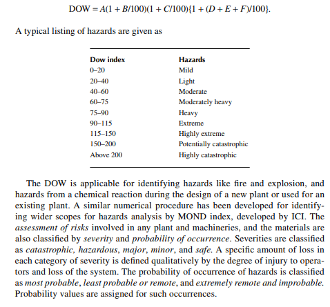
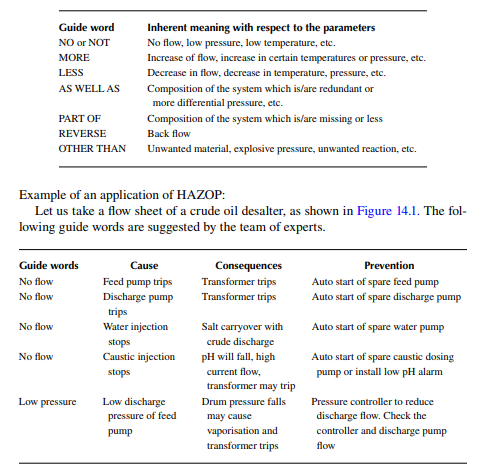
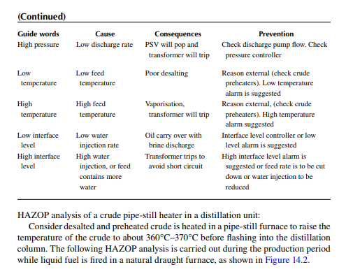
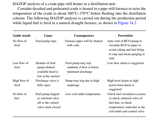
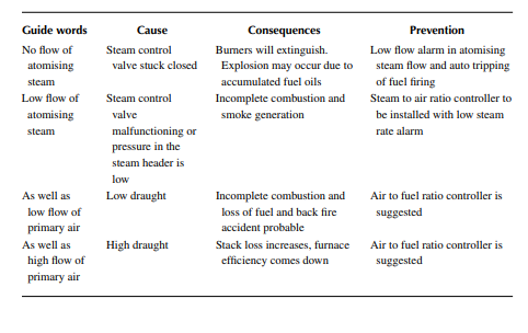
Hazards and operability, or HAZOP, is applicable for the operation of a batch or continuous plant. This is applied over a selected portion of any plant or the entire plant. This method applies in stages during the design, commissioning, and operation of a plant. For an existing plant, ranking of hazards is carried out using the DOW or MOND index to identify the potential hazards. A safety audit is then carried out to list the possible safety facilities. Past occurrences of unusual events are listed. Usually, a check list of the materials, unit operations, layout, and hazards are prepared. A fl ow sheet of the plant is then studied with respect to certain guide words or events. Possible reasons for the deviation or faults at these events are diagnosed and the consequences of such a deviation are eliminated by certain modifi cation or action. Modifi cation may involve the introduction of a controlling instrument, or the removal or extension of a pipe, provision of a vent or drain, etc., which were not originally present in the fl ow sheet or piping and instrumentation diagram of a plant. The following is a list of some of the guide words used in the HAZOP. These guide words are carefully prepared by experts relevant to the plant and equipment under study