13.1 CONTROL HARDWARE
Modern chemical plants are automatically controlled with the objective of achieving the highest productivity with minimum human intervention. Both the process control logic and strategies of control have undergone a sea change owing to the transformation of the analogue environment to a digital one. The automatic process control in a plant consists of three groups of elements—hardware, software, and the transmission lines. Hardware includes sensors/transducers, transmitters/signal conditioners, controllers, and fi nal control elements (control valves, switches, solenoids, motors, etc.). The software is the control algorithms or programs residing (or downloaded from the host computer) in the controllers, according to which output signals of controllers are generated.
13.1.1 HARDWARE
Hardware instruments are classifi ed as four elements: primary, secondary, controlling, and fi nal control. The sensor or transducer generates the primary signal and the transmitter (secondary element) sends the signal (carrying the primary signal) to the controller (sometimes trimmed through a signal conditioner to make the signal acceptable to the controller). The primary signal is usually obtained or converted in the form of electrical voltage or current (analogue signals). The controller receives the signal (the process variable, PV) in terms of electric voltage (milli to few volts) or current (4–20 milli ampere) as the signal accepted by the controller, compares it with the desired set point (SP), and generates the corrective analogue signal or power, which actuates the fi nal control element. This process of measurements and actuating actions is repeatedly carried out in the controlled system (control loop) as a guard to maintain the desired SP (or to follow the SP) under any circumstances of load fl uctuation or SP variation. Current computer controlled systems, such as a supervisory control and data acquisition (SCADA) system, uses the analogue transmitters with “stand alone” microprocessor controllers in the fi eld, which are capable of communicating to the supervising computer/computers located in the control room. Communication is carried out by the digital signal only. Hybrid analogue remote terminals (HART) are also being used for handling both analogue and digital signals for communication. With the ever-reducing size and cost of IC chips in the digital industry, almost all the analogue electrical gauges, transmitters, controllers, and even control valves are being rapidly replaced. Today’s controllers are capable of receiving and generating both analogue and digital signals. These usually communicate through an RS485
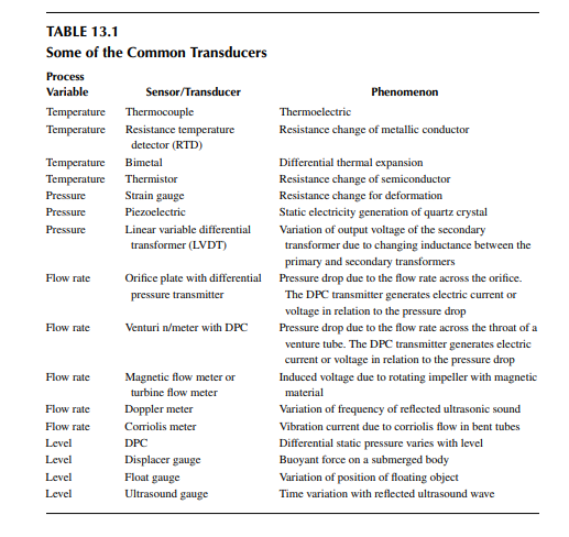
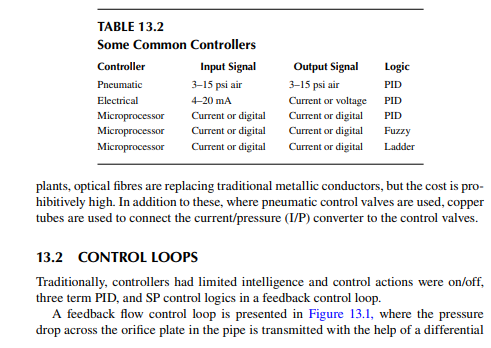
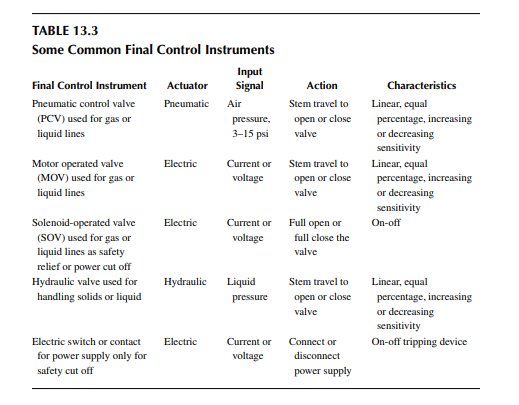
or standard IEEE communicating port through which computers can communicate to large numbers (as high as 50 or more loops) of controllers at a distance of a few feet to a few kilometres. Microprocessors or programmed logic controllers (PLC) are being widely used in the industry because of their low cost (Tables 13.1 through 13.3).
13.1.2 CABLES
Apart from the controlling instruments, transmission wires or cables play an important role in deciding the speed and cost of automation. A variety of cables are required for a controlled system. For example, (1) a cable connecting the sensor to the controller, (2) a cable connecting the controller to the control valve, (3) a cable connecting the controller to the host computer, and (4) a cable connecting the computer network. The transmission of signals from the sensor to the controller and from the controller to the fi nal control element is carried out by conducting copper wires (for electrical or digital signal). In order to enhance digital communication between the loop controllers and the host computers, optical fi bres are the most suitable medium. In many
13.3 THE PROCESS PIPING AND INSTRUMENTATION DIAGRAM
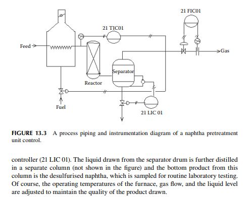
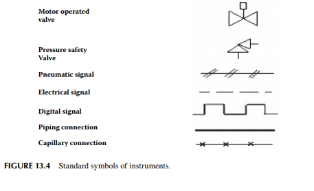
It is noted in Figure 13.3 that the sensors, controllers, control valves, control signal lines, and the process fl ow pipelines have been depicted with certain symbols as it is necessary to distinguish the process equipment, connecting processes, and the corresponding controlling instruments in the fi gure. In addition, code names like 21 TIC 01, 21 FIC 01, and 21 LIC 01 have been used where TIC, FIC, and LIC are, respectively, types of controllers as temperature, fl ow rate, and level indicating controllers. The process unit, the naphtha pretreatment unit, is designated as “21” and the instrument number is given an address of “01.” These symbols and code numbers help in identifying the processing unit and instruments as well. The process piping and instrumentation diagram with these symbols of instruments help in understanding the connectivity of processing steps and the control strategy. Though these symbols of instruments and process may differ from vendor to vendor, some commonly accepted standard symbols of instruments are presented in Figure 13.4.
13.4 CONTROL SOFTWARE
The control programs residing in the memory of the controller is the control software. For instance, a traditional control equation is a proportional-integral-derivative (PID) relation as mentioned below.
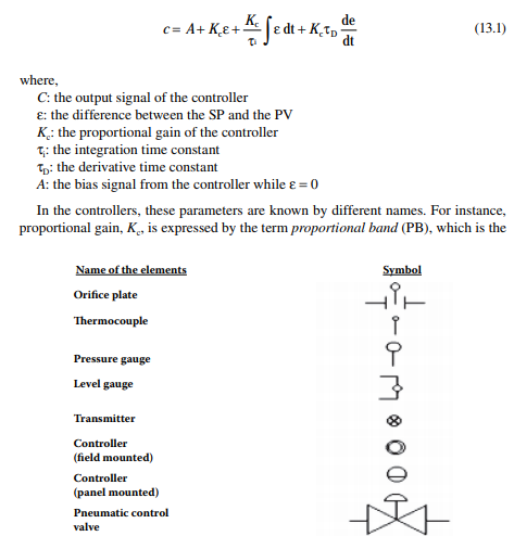
ratio of the error to the span of the controller output scale, which causes the control valve either to fully open or fully close. In fact, this becomes the inverse of Kc, i.e., the greater the value of PB, the smaller the value of Kc. In order to increase the speed of response, it is desirable to select a lower value of PB. Of course, too low a PB value will cause wide fl uctuations in the response, and control will be diffi cult. The integration time constant, τi , is expressed by the term as the reset time which is, in fact, the inverse of τi . The derivative time constant, τD, is also known as the rate time, which is the same as τD. If these parameters, PB, rest time, and rate time are not properly selected, the controller will not act properly. Selection of these parameters is tricky and they are selected by certain tuning methods, like the Ziegler–Nichol method or the Cohen–Coon method. Discussions of these methods will be found in books on control dynamics. Modern controllers are capable of self-tuning these parameters. Hence, if the controllers’ performance are not satisfactory due to delays, too many fl uctuations in the controlled variable, abnormal overshoot or undershoot, etc., tuning must be done and if the problem does not improve, instrument maintenance personnel must be called in to rectify the problem. Nowadays, digital programs are used to change the control equations of the input and output signal of a controller, as a result of which a suitable control algorithm is implanted in the controller. Even PID control actions are carried out successfully with an auto-tuning facility (both offl ine or online) in certain control variables, but PID control is not successful for many processes due to non-linearity and other complex dynamic problems, rather they are being replaced by a process-friendly model predicted algorithm, which has the capability of online process identifi cation and tuning. Artifi cial intelligence is also implemented for online fault diagnosis and action. In certain processes where control variables are not measurable, they are predicted or inferred and controlled by an inferential control model. The expertise of the plant operators’ knowledge can also be implemented for such a complex plant control. Uncertain external events, such as fl uctuation in market price and demand for products, exigencies, etc., are also taken care of in the controlled software. SPs that were earlier decided by the operators, engineers, or the managers, are now replaced by control software (a management information system) where the standard decisions are chalked out by the intelligent software itself and target SPs are delivered to the controllers without the need for human intervention. Finally, the success of the process control relies on the functions in the analogue controllers (electrical circuits) or the programs (software) in the digital controllers, according to which an output signal is generated by the controller. Various types of programming languages are involved in building control software. For example, high level languages like Visual Basic and Visual C++, are commonly employed for the programs loaded in the host computers, assembly languages are used in the loop controllers, and ladder logic programs are loaded in the PLC controllers. Programming skill of the control panel operators is not required as they are involved in changing certain entries in the front panels of the consoles or the controllers. Good programming skill is essential for addition or modifi cation of the programs loaded in the host computers. If it is necessary to build or modify the control software by the automation personnel in the users’ company, it is essential to collect the protocols of the controllers and its accessories from the vendors. The protocols of
the communicating controllers are the string of data sent and received by them to the computer, which must be compatible with the BAUD rate, parity, data structure, etc. This can save spiralling expenditure of software maintenance in the near future. Much of the software loaded in the host computers’ library is maintained by the software vendors on a contract basis. Operators and managers are trained to handle the parameters as needed for plant operation and management. Hence, little programming skill is required for the users of this software. Required assembly programs or ladder logic programs are usually downloaded from the archives of the host computers to the loop controllers’ memory by authorised operators or engineers of the plant.
13.5 DISTRIBUTED CONTROL SYSTEM
In the beginning, digital control was introduced as a direct digital control system where the input signals were directly fed to the computer and the output signal was used to drive the control valve. An analogue to digital converter (ADC) was used to convert the input signal from the transducer and a digital to analogue converter (DAC) was used to convert the digital output of the computer to an analogue signal to drive the control valve. In such a system, computer workstations with more than two or three CPUs were used to drive the control system. In this system there was a danger of upsetting the controlled system due to any fault in the computer, which acts as the controller. This problem has been overcome in the distributed control system (DCS). Today, the majority of modern plants use a DCS. In a DCS, a workstation with supervising computers are connected to the loop controllers (microprocessors or PLC), which are distributed throughout the process, each performing locally to control the respective control variables. High-speed communication is through a two-way fi eld bus to transmit process data (in the coding and decoding of appropriate protocol) from the local controllers to the computer/computers in a centralised control room and vice versa. Data includes sensed PVs, SPs, controller parameters or program parameters, alarms, sensors’ type, address and the status of online connectivity of sensors (like sensor open or online, etc.), output signal from controller delivered, control valve position (full open or closed, etc.), etc. PV signals are the read-only (RO) type, which cannot be changed from the console but can be recorded and visualised. Output power, modes of action (manual, control, cascade, tuning, alarms, etc.), parameters of the controllers, SP, etc., are read-write (RW) type signals. These can be changed from the consoles in the control room. Controller parameters can be changed in the confi guration mode or tuning mode from the consoles. Panel operators are permitted to change certain intermediate SPs (RW) to adjust the process conditions and can make a print out and save the information. Only authorised personnel or managers are allowed to change the vital SPs, such as target throughputs in a plant, control programs or parameters, accessing of records of vital operating data saved, confi gured values, addresses of controllers, etc., which are not accessible to the plant operators. An additional data bus is provided to access the operating conditions of the plant for management decisions. An operating system like WINDOWS, or any other operating system may be chosen for digital communication and control. Any fault in the host computer will not upset the controlled system as it is the controllers’ chip memory that will maintain the control action in
their respective loop at the previous set operating conditions. Redundant paths are always provided to avoid failure in communication and control actions.
13.6 THE CONTROL ROOM
The control room is where the controller can be operated to change the SPs, record the PVs, tune the parameters of the controller, and have correcting signals delivered to the control valves. Sensors and control valves are mounted over the appropriate fi eld or location on the equipment and pipelines of any process unit to be controlled. Controllers are usually placed in the control room far from the fi eld locations. Sensors are connected through long cables of wires or optical fi bre lines, ranging from a few feet to more than a kilometre in length, terminating at the controllers located in the control room. Output signal lines from the controllers are then drawn from the control room to the actuators of the fi nal control elements. All these controllers, in fact, fetch measurement signals or PVs continuously, evaluate error (ε) by comparing with the desired SPs and deliver an output signal as a function of the error (ε). In the DCS, these controllers are interfaced with high-speed desktop computers with large memory space. The necessary software is loaded onto these computers to access the individual controller’s parameters, the signals received, and the signals delivered. The controllers communicate with the computers through digital input/output signal lines connected through RS485 or IEEE standard ports. In the DCS, the controllers are supervised by the computers (i.e., the computers can access any individual controller by their respective address and recover the measured PVs, change the SP values, tune the controller as and when required, record the data, etc.). In case of computer failure due to some unforeseen event, the controllers existing data will be unaffected and the control action will continue without fail. The control room is provided with a clean and temperature-controlled environment in order to protect the computers, controllers, and recording/printing devices and also to provide a comfortable working space for the panel operators and engineers for decision making. A modern control room in a refi nery.
13.7 CRUDE THROUGHPUT CONTROL
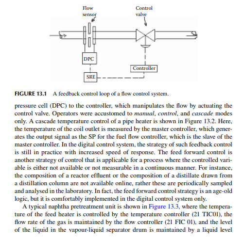
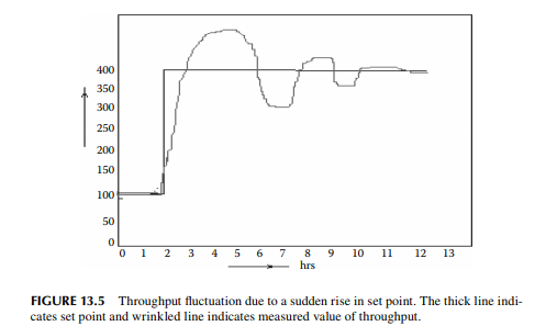
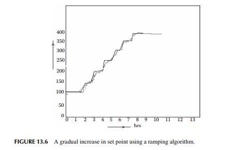
Control of crude throughput means that the fl ow rate or throughput is maintained at the desired throughput or fl ow rate. As shown in Figure 13.1, an orifi ce plate is placed in the pipeline through which crude is pumped. Upstream or high pressure (HP) tapping and downstream or low pressure (LP) tapping across the plate are connected through a DPC transmitter, which delivers a current signal in relation to the pressure difference (hence relating the fl ow rate). This current signal enters the controller, which is compared with the SP, the desired fl ow rate and computes an output signal according to the PID equation as given in Equation 13.1. However, the adjustment of the fl ow rate must be done carefully by smooth SP adjustment since a change in the SP does not guarantee an immediate response without fl uctuations above and below the SP. It will take some time for these fl uctuations to subside before a stable response is achieved. For example, if the present throughput is 100 m3/h and it has to be raised to 400 m3 /h, the panel operator will adjust the SP in gradual steps, e.g., 50 m3 in 1 h, until the process measurement reaches 150 m3/h, then 50 m3 in another hour to 200 m3/h, and so on until 400 m3/h is achieved. This type of gradual SP increase is called a ramping algorithm, where the slope of the ramp, in this case 50 m3 in 1 h, is selected. This is done to avoid a wide fl uctuation in throughput if an attempt was made to increase it from 100 to 400 in one go in a short space of time. Similarly, while throughput has to be reduced from 400 to 100 m3 /h, a gradual reduction, selecting a ramping algorithm as described above, is carried out to avoid a violent fl uctuation in the fl ow rate. Typical SP adjustments from 100 to 400 m3 /h of throughput are presented in Figures 13.5 and 13.6 for a sudden change and a gradual change in SP, respectively.
13.8 DESALTER CONTROL
As already discussed about an electrical desalter, as shown in Figure 13.7, pressure and interface level control are widely practised. However, pH control is rather wieldy as compared to pressure or level control due to non-linearity of the pH. Pressure control is desirable to avoid vaporisation within the desalter because vapour formation may cause explosion due to the heat dissipation from the electrode plates as soon as the liquid phase disappears. A pressure controller measures the pressure within the desalter and manipulates the discharge fl ow of desalted crude oil. Usually, a minimum pressure, depending on the type of crude, must be set (typically about 8 bar) to avoid vaporisation. In case the pressure rises above the maximum allowable operating pressure, a safety valve pops (opens) for safe discharge of fl uids (gas or liquid), usually to a fl ash zone of the distillation column nearby or to a fl are line. In both the events when low pressure (LP) or high pressure (HP) occurs, the transformer is switched off with the help of a power tripping device. The other important control is the oil–water interface level below the electrode plates. In many refi neries, this level is usually controlled manually by monitoring
the presence of water through multiple sampling pipes within a distance from the minimum to maximum allowable limits. In case the water level touches the electrodes, there will be a short circuit and it may cause explosion. In order to avoid such situations, the transformer is switched off by a power tripping device as soon as the water level reaches a certain percentage of the level, which is well above the danger level that may cause a short circuit. Too low a level of water may cause draining of the crude from the discharge line for water. However, in case of automatic control of the interface level, a level controller and a control valve at the discharge must be provided, as shown in Figure 13.7. Alarms are usually fi tted with cutoff valves (usually
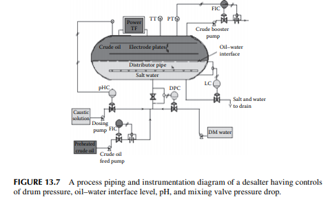
solenoids) at the low and high values of pressure and water level. The other vital control is the water injection rate, which is crucial for the desalting operation. This rate is controlled by a controller that measures the pressure drop across the mixing valve.
13.9 ATMOSPHERIC DISTILLATION COLUMN CONTROL
In the crude distillation unit, the distillation column has two sections, the rectifi cation section and the stripping section, respectively, above and below the fl ash zone. Gases and naphtha are drawn as vapour from the top of the column, kerosene and diesel (with additional distillate heavier than diesel like jute batching oil (JBO) in some columns) are drawn as the liquid products from the rectifi cation section, and residue (reduced crude oil, RCO) is drawn from the stripping section bottom. However, kerosene, diesel, and JBO are further stripped in the side strippers. Control of the top pressure and temperature, fl ash zone temperature and pressure, fl ow rate of over fl ash (which is a split stream taken from the plate above the fl ash zone), overhead refl ux and circulating refl uxes, liquid levels in the plates of the column and strippers, steam rates at the bottom of the column and the strippers, are vital to maintain the quality of the products.
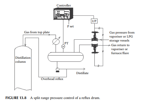
13.9.1 REFLUX DRUM PRESSURE CONTROL
The top pressure of the column is dependent on the pressure in the refl ux drum. Control of the pressure drum is carried out by the split range control strategy. The drum pressure is increased in two ways—by the vapours leaving the top plate and from the pressure of the vaporiser drum or from a high pressure source like liquifi ed petroleum gas (LPG) storage vessels. On the other hand, drum pressure is reduced by expelling it to return to the vaporiser or fuel gas consumption points, e.g., furnace or fl are. Such a connection is presented in Figure 13.8. There are two control valves, one allows gas entry from the vaporiser and the other allows gas exit to the vaporiser or furnace or fl are. If these valves are air pressure operated in the range of 3–15 psi instrument air, the following actions will be carried out to manipulate the pressure in the drum. The valve at the gas entrance is air operated and is normally open, i.e., air to close, thus it fully opens at 3 psi and starts closing as the pressure rises from 3 to 9 psi. It is completely shut when the pressure rises to or above 9 psi. This valve is normally closed, i.e., air to open from 3 to 9 psi air pressure, starts opening as the pressure rises from 9 psi, and completely opens when the pressure rises to 15 psi. The controller generates a signal (direct acting mode) as the pressure of the drum increases, but below the SP, in the range of 3–9 psi, gas enters the drum to fi ll the drum while the gas exit valve is shut. While the drum pressure goes above the SP, the controller will still increase the signal pressure above 9 psi, actuating the exit valve to start opening to reduce the pressure in the drum and fully opens the valve if the pressure signal rises to 15 psi.
13.9.2 REFLUX DRUM LEVEL CONTROL
Control of the liquid level in the refl ux drum is essential because a suffi cient level must be maintained to make it pumpable as the overhead product and as refl ux as
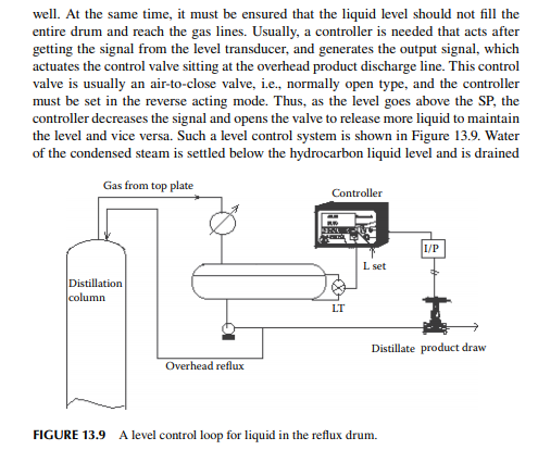
off through a conical pipe or boot (not shown in the fi gure). High-level and low-level alarms are also required in case of problems with the condenser, discharge pump, or column troubles causing widely fl uctuating vaporisation and condensation, or even due to the effect of a malfunctioning controller.
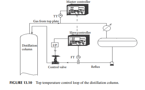
13.9.3 TOP PLATE TEMPERATURE
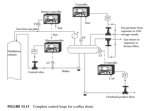
This is controlled by a cascade control strategy, as shown in Figure 13.10. The temperature of the vapour leaving the top plate is measured and transduced to a controller, which generates the necessary signal to actuate another controller to manipulate the refl ux fl ow rate to the top. A complete assembly of the pressure, level, and temperature control loops for a refl ux drum is presented in Figure 13.11.
13.9.4 DRAW PLATE TEMPERATURE
Liquid is held up over a plate to a height provided by the weir. This is provided to maintain a certain liquid level on the plate through which upcoming vapours pass through distributors, such as bubble caps, valves, nozzles, etc. This helps to intimately mix the vapours and liquid for maximum mass and heat transfer, aiding purifi cation of the more volatile components. Liquid overfl ows the weir through a downcomer slit, down to the next plate below. Certain plates are selected for drawing a portion of the liquid as the side product, such as kerosene, diesel, JBO, etc. Usually, drawn products are further stripped in a side stripper where the liquid level is maintained by a level controller, as shown in Figure 13.12. The controller increases the drawing rate as the level increases over the desired SP and vice versa. If the level is maintained low by setting a low level, the draw will increase. The effect will reduce condensation and increase vaporisation and the plate temperature will rise. The end point of the draw will increase. In case no level controller is used, a fl ow controller
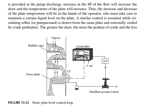
fuel consumption in the crude heater. But the operator must not make the plate dry, which will upset the entire column operation.
13.9.5 OVERFLASH RATE
The fl ow rate of overfl ash, which accounts for 2%–3% of the crude throughput, is controlled by a fl ow controller that allows fl ow from the plate above the feed plate down to the fl ash zone, according to the SP selected by the operator.
13.9.6 FLASH ZONE PRESSURE AND TEMPERATURE
The pressure and temperature of the crude oil exiting the crude heater determines the fl ash zone temperature and pressure, i.e., the manipulation of the discharge pressure and temperature at the upstream of the fl ashing nozzle determines the fl ash zone conditions.
13.9.7 BOTTOM TEMPERATURE
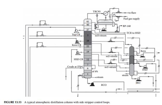
Like any other draw plate, the bottom temperature is dependent on the RCO draw, which is manipulated by a level controller to maintain the level at the bottom of the column. However, steam rate through the bottom also affects the bottom temperature. A steam fl ow controller is used to manipulate the fl ow rate of steam, which needs to be changed for adjustment of the amount of light distillate components in the RCO. Too high a steam will cause heavier fractions to be carried over with the upper plate draws and too low will cause carryover of light distillates with RCO. A high steam to crude ratio may lead to a high-water condensation rate, which may cause water in the top and side products. A typical piping and instrumentation diagram of an atmospheric column with side stripper is shown in Figure 13.13.
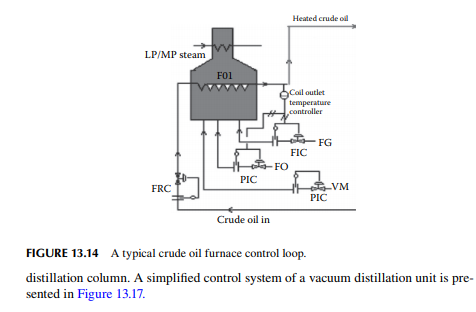
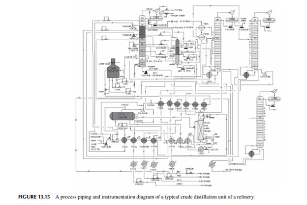
13.9.8 FURNACE CONTROL
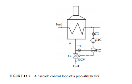
The coil outlet temperature of the furnace is controlled by a cascade control system where the master controller gets its input signal from the thermocouple from the coil outlet fl uid and a slave controller manipulates the fuel to the furnace. This is shown in Figure 13.14. A complete piping and instrumentation diagram of a crude distillation unit of a refi nery is presented in Figure 13.15.
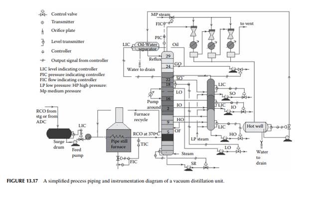
13.10 VACUUM DISTILLATION CONTROL
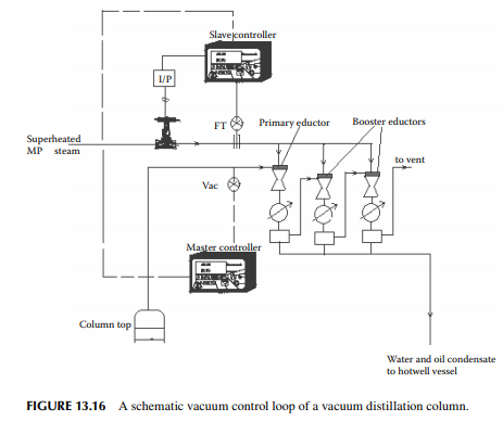
Vacuum distillation of RCO in a multiplated distillation column is carried out at a top pressure of around 60–80 mm Hg abs, which is created by more than one steam eductor. The vacuum is controlled by the steam fl ow rate in the eductors. Usually, a cascade control is advised for accurate control owing to fl uctuation in the supply pressure of steam. A conceptual control system is shown in Figure 13.16. Draw plate temperature and level are controlled similarly as described for the atmospheric
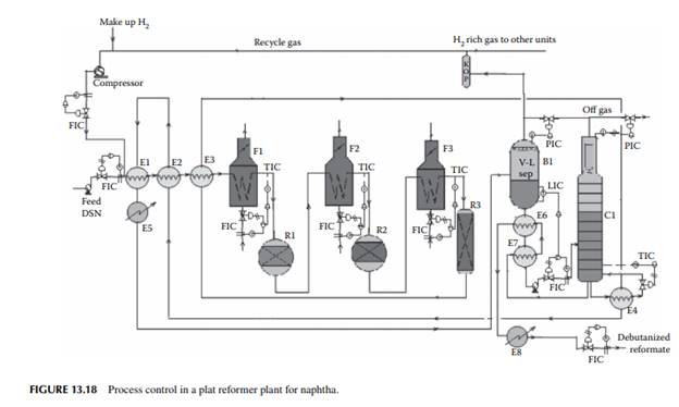
13.11 REFORMER UNIT CONTROL
There are a variety of reforming methods, however, a discussion of the control system of each type is out of the scope of this book. A fi xed bed three-stage platformer will be discussed here. The details of the process have been discussed earlier. The desulfurised feed naphtha fl ow rate is controlled by a fl ow controller. After preheating with the hot product from the last reactor, feed is further heated in a furnace before entering the fi rst reactor. Because the endothermic reaction temperature of effl uent from each reactor falls, reheating is done by the intermediate furnaces. The temperature of the furnaces is controlled by cascade controllers. The level in the fl ash drum separator is maintained by a level controller before the liquid from the drum enters the debutaniser column. This debutaniser column is, in fact, a multiplated distillation column. The top pressure and temperature are controlled by separate pressure and temperature controllers. The bottom temperature is controlled by a separator controller at the reboiler drum. This is explained in Figure 13.18. As shown in Figure 13.18, local fl ow controllers installed at the feed entry, recycle gas and products fl ow lines. The coil outlet temperatures of the furnaces are controlled by cascade TIC and FIC controllers. The vapour liquid separator (fl ash drum) level is controlled by a cascade control with LIC and FIC controllers. The debutaniser bottom temperature is controlled by a TIC controller. The pressures of the fl ash drum and the debutaniser column are controlled by PIC controllers connected with the off gas/fl are line.
13.12 FLUID CATALYTIC CRACKING UNIT CONTROL
The fl uid catalytic cracking (FCC) unit, as described elsewhere in this book, contains a reactor and a regenerator. A modern reactor has a long riser tube, where the
cracking reaction is carried out in a continuous fl uidised bed of catalyst and the feed hydrocarbon oil is atomised with medium pressure (MP) steam. The residence time or catalyst–hydrocarbon contact is about 2 sec at a temperature of around 600°C. As soon as the reaction is over, the catalyst is separated from the cracked product in a large diameter vessel where the riser terminates. The spent catalyst falls into the annular space between the riser end and the disengagement vessel. This accumulated catalyst is stripped from the remaining hydrocarbons and overfl ows to a regenerator vessel, where coke on the catalyst surface is burnt in air. The hot regenerated catalyst is then lifted to the reactor along with preheated feed and steam. The reactorregenerator unit is controlled for various operating variables. Vital control strategies are listed below.
13.12.1 REACTOR OUTLET TEMPERATURE CONTROL
The exit temperature of the cracked product is measured and a temperature controller (TIC) manipulates the fl ow of the hot regenerated catalyst from the regenerator to the reactor with the help of a slide valve (control valve), the stem of which is hydraulically actuated. A pressure drops controller (PDC) across the same control valve is also used to measure and manipulate the catalyst fl ow. Thus, there are two controllers in action with a single control valve. As the temperature controller increases its signal for raising the catalyst fl ow rate to the reactor, the pressure drop across the control valve increases. Since too high a velocity of catalyst through the valve may
cause erosion of the control valve and pipeline and will also disturb the desirable fl uidisation behaviour, it is necessary to maintain the allowable limit of pressure drop across the control valve. In this event, a limit switch acts to disable the TIC signal and enable the PDC signal instead, i.e., while the upper limit of pressure drop across the valve is reached due to the action of the temperature controller, the PDC controller will actuate the valve to reduce the fl ow rate, overriding the action of the temperature controller. An additional temperature controller is also provided to reduce the reaction temperature with the help of the fl ow of quench oil (usually light cycle oil) to avoid unwanted overcracking of the products.
13.12.2 LEVEL CONTROL OF THE CATALYST BED IN THE STRIPPER SECTION OF THE REACTOR
A level controller is used to manipulate the exit fl ow of the spent catalyst through a slide control valve. In this case also, a PDC is used to manipulate the fl ow rate through the valve, overriding the level controller. The action is similar to the strategy described for the reactor outlet temperature control.
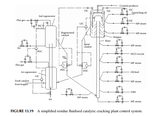
13.12.3 PRESSURE BALANCE BETWEEN THE REACTOR AND THE REGENERATOR
The pressure in the reactor section is governed by the pressure of the distillation column, where the cracked products are separated and no additional pressure control loop is added to the reactor top. However, pressure controllers are provided in the fl ue gas lines of the fi rst and second stage regenerators. The pressure over the regenerators is so controlled that the fl ow of spent and regenerated catalyst is maintained. The control strategy can be understood from the simplifi ed process piping and instrumentation diagram of a typical modern RFCC unit, as shown in Figure 13.19.
13.13 FAIL-SAFE DEVICES
During failure of the supply of power, steam, and instrument air and also due to accidents, certain safe operating conditions are maintained with the help of inbuilt safety arrangements. Usually, the failed situations are classifi ed into three categories: 1. During normal running conditions 2. During planned shutdown 3. During accidents or emergency shutdown
13.13.1 NORMAL RUNNING CONDITIONS
Normal running conditions assume that the power and utilities supply are uninterrupted while the equipment and machineries need to be protected so that the maximum or minimum limits of operating conditions are not violated. Controlling instruments are used to maintain the normal limits of operation only, but additional instruments, known as securities, such as safety valves or switches or varieties of tripping devices, are used to maintain maximum or minimum limits for the safety of the equipment and machineries. Some of these common safety arrangements are listed below.
3. In case a vessel is fi lled with gas at HP and the pressure rises to approach the maximum limit, a pressure safety valve will pop to release the gas from excess pressure.
4. In case of a rise in temperature approaching the maximum limit, a safety fuse is used to protect any equipment from overheating.
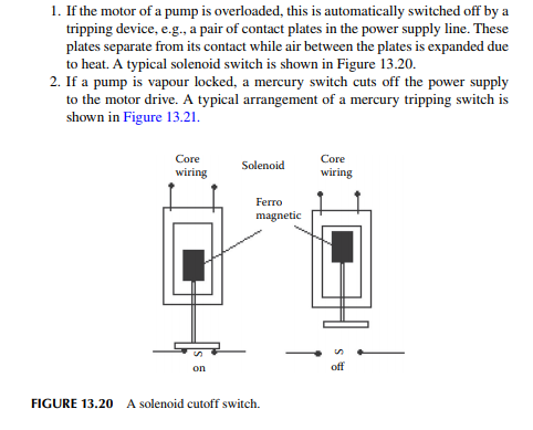
5. In case a furnace fl ame is extinguished for a certain reason, the fuel fl ow to the burners must be shut with a solenoid-operated valve in the fl ow line. Alternatively, the solenoid valve disconnects the instrument air supply to the fl ow control valve (which is normally closed type (N/C) valve so that it closes in absence of instrument air) to shut. It is to be noted that there is a common fuel circulation circuit for all furnaces and hence it is not wise to shut fuel pumps while only one furnace is extinguished.
6. In case of a high level of water, excess pressure exceeding the limits, feed pump or booster pump failure in a desalter unit, the power supply to the transformer will be switched off with the help of a cutoff switch. There are each such operations carried out for the safety with the help of instruments known as securities, however discussion of all of these operations are out of the scope of this book.
13.13.2 DURING PLANNED SHUTDOWN
Planned shutdown is carried out for large-scale repair, cleaning, painting, or modifi – cation jobs. This shutdown is judiciously carried out in sequence. First, the processing units are shut down in a sequence from the downstream units to the main unit. During this operation, power generation is also reduced gradually as the demand comes down and, fi nally, the power plant is shutdown. The safe operations involve a gradual reduction in furnace temperature to avoid thermal shock to the equipment.
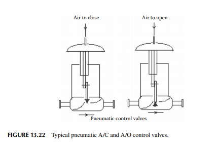
The SPs of the controllers are mostly handled by the ramping algorithm for a reduction in the temperature of the furnaces and the fl ow rates of the feed streams. Manual operations and monitoring are increased during these shutdown steps. A brief account of these steps is given in Chapter 14. Control valves are so selected that these will be fully open or fully closed when the instrument air supply is stopped. Usually, the selection of these valves must be judged by the designer so that any mishap can be avoided in control signal failure or instrument air failure. For instance, in a fl ash drum, the vapour line should be provided with an air-to-close valve, i.e., a normally opened (N/O) control valve so as to permit exit of the vapour from the drum at the time of failure of the instrument air or control signal. Similarly, the fuel supply line in a furnace or the steam (or hot fl uid) supply to the reboiler of a debutaniser should be provided with an air-to-open control valve, i.e., a normally closed valve, to assist in stopping the fuel or steam fl ow, respectively, at the time of instrument air supply or controller signal failure. Typical pneumatic air-to-open and air-to-close valves are shown in Figure 13.22.
13.13.3 DURING ACCIDENTS OR EMERGENCY SHUTDOWN
Sudden failure of machineries or equipment causes an emergency shutdown. Accidents due to fi re in a refi nery are commonplace. An emergency shutdown of the affected unit and sometimes other adjoining units becomes inevitable to contain the devastation. In this situation, the power supply is stopped either by inbuilt security instruments or by the power supply grid. An automatic sprinkler or water spray may be started by the temperature sensitive fuses or evacuation of fl uid through normally open control valves, as the case may be. All the cutoff solenoid or switches should work in tandem to protect the unaffected plant and machineries while fi re fi ghting is carried out manually.
13.13.4 POWER PLANT FAILURE
Large refi neries and petrochemical plants have their own power plants (captive power plants) to provide an uninterrupted supply of electricity and steam. If a power plant is suddenly shutdown for any inadvertent exigency in the plant other than a planned shutdown, necessary inbuilt safety must be envisaged in the plant. It is easily understood that if the running machineries with electric drives suddenly stop, immense damage will be caused to the plant, even accidents may occur. For this, it is essential to have certain safety devices to allow necessary actions to eliminate any catastrophic situation. In case of partial failure of a power plant, e.g., a power grid problem, a frequency fl uctuation, etc., or the generation of electricity while the steam generation is unaffected, all the vital machineries should have steam-driven spares that should automatically start, to protect the equipment and machineries. Such a sudden shutdown of a power plant will affect the supply of steam, instrument air, and cooling water, in addition to the power. As a result, the cooler or condenser will be out of service and the gases or hot fl uid need to be evacuated to avoid pressure development (temperature increase) by the normally open control valves or pressure safety valves or temperature safety valves. Thus, process instrumentation and control of any plant encompasses a thorough knowledge of instrumentation hardware and software with the necessary inbuilt securities strategically located to save the plant and machineries from the various kinds of failures as discussed in this section.
13.14 STANDARD SIGNALS IN PROCESS CONTROL
Electrical voltages or current (dc) signals are generated by the transducers and transmitted, recorded, and processed by the remote controllers. The standard current signal lies in the range of 4–20 mA dc. Sometimes, 0–20 mA is also used. Common voltage signals are 0–10 V and 1–5 V, all in dc. Most modern controllers are capable of accessing and delivering milliamperes, millivolts, and voltage signals. All the instruments connected must be compatible with the respective signals to operate them. Pneumatic control valves are actuated by pneumatic air pressure signal in
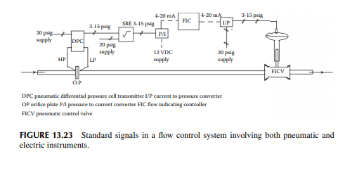
the range of 3–15 psig from the current to pressure or voltage to pressure converter. Controllers are powered by 24–30 V dc or 230 V ac with a dc converter. Some of the common standard signals are shown in a typical fl ow control loop in Figure 13.23. Here, the DPC transmits an air pressure signal in relation to the pressure drop across the orifi ce plate. This signal is linearised by a square root extractor (SRE) that generates a pneumatic signal in relation to the signal received from the DPC transmitter. This signal is then converted to an electric current signal by a pressure to current converter (P/I), which enters the fl ow indicating controller (FIC). The output signal from the FRC is again converted back to the air pressure signal by a current to pressure converter (I/P) in order to actuate the fl ow indicating control valve (FICV). In refi neries and petrochemical plants, explosion or fi re may occur due to high temperatures and electric sparks. Therefore, it is essential to protect the electric lines by fl ame-proofi ng gas pressure or with proper insulation and safety fuges, etc. Such type of barrier between the explosive area containing hydrocarbon vapours or liquid or even explosive dusts and the high voltage electric cables or machines is known as the Zenner barrier