6.1 LAYOUT OF PETROLEUM AND PETROCHEMICAL PLANTS
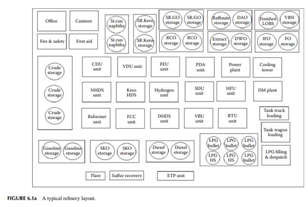
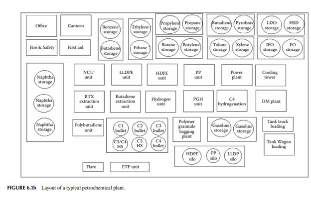
A refi nery or a petrochemical plant consists of various plants and equipment suitably grouped and located in various sites known as processing units. Other facilities include off sites, power plant, cooling tower, water conditioning plant, quality control laboratory, and service centres, such as canteen, fi rst aid, fi refi ghting facilities, attendance registration offi ce of employees, and administrative offi ces. Typical layouts for a refi nery and a petrochemical plant are presented in Figures 6.1a and b.
6.2 PROCESSING UNITS
Various processing units in a refi nery and a petrochemical plant have been discussed in Chapters 3 and 5, respectively. The number of processing units is determined by various factors, such as type, availability and price of feedstocks, demand for products, and environmental restrictions. Common units in a refi nery are crude distillation units (CDU), both atmospheric and vacuum, followed by stripping and separation processes, such as solvent extraction and crystallisation. Distillates are recovered from residues either by vacuum distillation or by solvent extraction. Thermal and conversion processes follow next. In fact, each conversion unit also consists of separation units, such as fl ash separation, distillation, and extraction. Processing units, e.g., CDUs, may house some other auxiliary units, such as a gas processing plant, a stabiliser, and a merox unit. A vacuum distillation unit (VDU) is usually separately located or included in a CDU. Other units are a furfural extraction unit (FEU), a propane deasphalting unit (PDA), naphtha hydrodesulfurisation (NHDS), kerosene hydrodesulfurisation (KHDS), a reformer, fl uid-catalytic cracking unit (FCC), diesel hydrodesulfurisation (DHDS), a vis-breaking unit (VBU), a bitumen treatment unit (BTU), a solvent dewaxing unit (SDU), and a lube base stock hydrofi nishing unit (HFU). In a naphtha-based petrochemical plant, the mother unit is the naphtha cracking unit (NCU), which includes cracking furnaces and product recovery units. Polymerisation units, e.g., linear low density polyethylene (LLDPE), high density polyethylene (HDPE), polypropylene (PP), polybutadiene, and other units, such as a benzene-toluene-xylene extraction (BTX) unit, a pyrolysis gasoline hydrogenation (PGH) unit, and a hydrogenation unit for butenes and butadienes (C4-hydrogenation), follow next. Each processing unit is separated by a physical boundary line from the other units is known as the battery limit of the unit. In this boundary, the incoming and outgoing lines of raw materials and products, chemicals, water, steam lines, etc., are suitably located for easy access during operation.
The distance between the battery limits of these units is determined by safety and maintenance regulations for easy accessibility during maintenance and in the event of an emergency. Roads and lanes are usually provided between the battery limits. Pipelines carrying gas and liquid are either overlaid or humed (underground) across the space between the battery limits.
6.3 OFFSITE FACILITIES
Off sites are areas where feedstock and its products are stored along with other chemicals necessary for processing. Off sites include facilities in addition to storage, blending, fi lling, packaging, loading, despatches, and effl uent treatment facilities. Usually, it is common practice to store raw materials and intermediate products near the user unit. For example, storage tanks for crude oil and straight run products are located near the CDU; similarly, storage of reduced crude oil (RCO) and vacuum distillate tanks are located near the VDU unit. Storage facilities are strategically laid out so that the pump houses are as near as possible to feed the units. About 70% of the off sites are occupied by storage tanks, which are suitably housed in tank farms. Each tank farm contains a number of tanks storing similar products, fi nished or semifi nished, surrounded by a cemented bund to contain accidental leakage and drainage of oily water and rain water from the tanks. The advantage of such a tank farm is that it facilitates recovery of valuable products. Each tank farm is provided with a dyke or pit to facilitate the drainage of oil and water to its respective recovery unit through separate channels, e.g., open drains, or to channels leading to the effl uent treatment plant (ETP). In a refi nery, the fi lling of liquifi ed petroleum gas (LPG) in cylinders and bitumen in drums are the most common fi lling operations. Similarly, storage of polymer granules and bagging and despatch are carried out in the off sites of a petrochemical plant. Bulk loading of various products in tank trucks, rail wagons, barges, and tankers are also included in the offsite facilities. Some of the offsite facilities also include fuel pumping and gas distribution network maintenance, effl uent water treatment, off gas treatment, and fl aring. Since storage constitutes the major function off site, a brief discussion of storage tanks follows. For feedstocks, products, and chemicals that have a high vapour pressure in ambient temperature, storage of these are usually carried out in fl oating roof or pressurised tanks or cryogenic conditions to avoid loss due to vaporisation. For example, crude oil, naphtha, and gasoline are stored in fl oating roof tanks where the vapours are contained and liquifi ed by the fl oating heads and thus do not allow vapour loss to the atmosphere. LPG is stored in pressure vessels (known as bullets) and spherical pressure vessels or Horton spheres. Ethylene is also stored in a pressure vessel at low temperature to keep it in a liquid state. Some of these storage tanks are discussed below.
6.3.1 FLOATING ROOF TANK
As shown in Figure 6.2a, a fl oating roof tank consists of a fl oating deck made of multiple chambers, which fl oats over the surface of the liquid stored. The deck (1) may be made of pontoon or multiple hollow steel chambers. The deck is supported by the buoyant force exerted by the liquid and fl oats up and down with the changing liquid
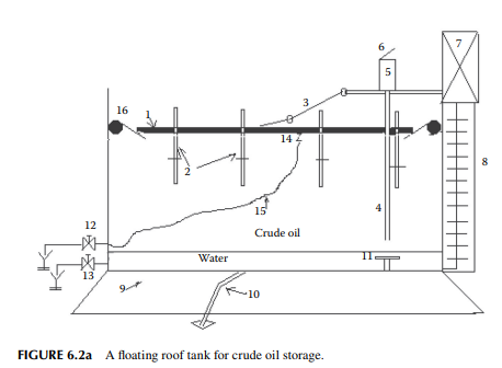
level. The circumference of the deck and the shell of the tank are sealed by springloaded rolling covers (16), which roll along the tank shell with the up and down movement of the deck. Accessories include a dip pipe (4) running vertically downward from the top of the tank, a fl exible steel drain pipe (15) attached to the deck for roof draining, a water drain pipe (13) at the bottom of the tank, and a swing ladder (3) over the deck hanging from the top (7) of the tank shell. The deck is also equipped with hanging supports (2, known as legs or spacers) for when the deck reaches the lower most position of the tank, allowing suffi cient space between the tank bottom and the deck for inspection and maintenance. Each leg passes through the fl oating deck with proper sealing. There are four or more numbers of legs which support the fl oating roof and these legs are hung on their upper stops while deck is fl oating. Deck rests on the lower stops of the legs while it is not fl oating. During this de-fl oated situation legs hold the entire deck on their lower stops providing work space above the bottom surface of the tank for cleaning and other maintenance jobs.
6.3.2 FIXED ROOF TANK
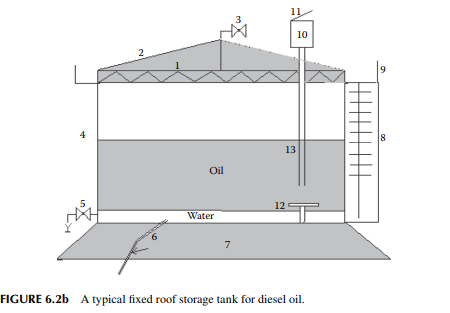
Products such as kerosene, diesel, vacuum distillates, and furnace oil (FO) are liquid at atmospheric conditions because of low vapour pressure. Therefore, these are stored in fi xed roof tanks. A typical fi xed roof tank is presented in Figure 6.2a, where the roof is supported over the top of the cylindrical shell of the tank, hence these roofs are also called shell or self-supported roofs. The roofs are not exactly fl at, but rather conical to avoid the accumulation of rain water. Hence, these are also known as cone roof tanks. For larger tanks, the weight of roof will be enormous, thus a separate bridge and column structure is provided to support these roofs.
6.3.3 PRESSURE VESSELS
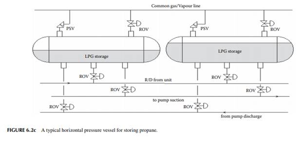
Gases, such as hydrogen, ethylene, propane, butane, and LPG, are stored in thickwalled pressure vessels. Gases that do not liquify can be stored in either horizontal or vertical bullets, but liquifi ed gases are stored in horizontal vessels to allow a large disengagement space for vapour within the tank. Typical pressure vessels are shown in Figure 6.2c.
6.3.4 HORTON SPHERE
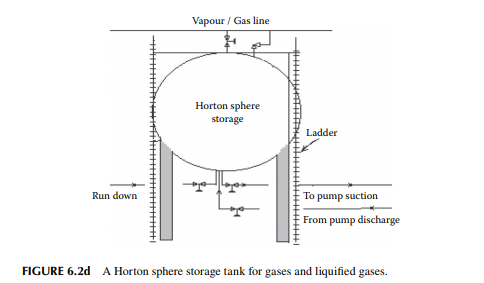
The cylindrical shape has a surface to volume ratio of 4/d and for the spherical shape it is 6/d, where “d” is the diameter. Hence, for spherical tanks larger surface area for cooling is available for the same volume to store. Usually, large spherical vessels are used for storing liquifi ed gases. These vessels are also known as Horton spheres. A typical Horton sphere tank is presented in Figure 6.2d.
6.3.5 ACCESSORIES
Each storage tank is provided with a datum plate slightly above the bottom of the tank to facilitate the standard measurement of the level in the tank by dip tape or dip rod. For small tanks, straight dip rods graduated with markings (in milimetres or centimetres or metres) are used to measure the level of liquid in the tank, but for large tanks, steel tapes, known as dip tapes, are used. For liquifi ed gases, direct level gauges or differential pressure gauges are employed to measure the liquid level. For gases, pressure and temperature are measured to calculate the quantity of gas stored in a pressure vessel. In fact, temperature is an important parameter to measure for all
types of products, whether they are liquids or gases. A dip tape is lowered through a pipe that terminates slightly above the datum plate. To maintain the gravity of fall, a bob made of brass or aluminium is attached to the tip of the dip tape. The dip pipe and the bob facilitate the straightening of the dip tape and do not allow swings sideways to avoid an error in level measurement. For white oils, such as naphtha, gasoline, kerosene, and diesel, which are not black and sticky, a special type of chemical (known as oil fi nding paste) is applied to the dip tape to identify the oil level. The presence of water in the tank is also measured and deducted from the total quantity. A separate chemical (water fi nding paste) is applied to the dip tape for measuring the level of water below the oil. In this dipping method, the dip tape is lowered until it touches the datum plate and the liquid level is read directly from the tape. This method is called the innage method of dipping. For viscous and sticky oils, such as FO, asphalt, and wax, the dip tape is lowered until it touches the surface of the liquid in the tank, i.e., the height of the empty space is measured rather than the height of the liquid, which is determined by deducting this from the reference height from the datum plate marked over the dip pipe or tank. This type of measurement is called the outage method of dipping. Each tank also bears marking of the safe fi lling height, cautioning the limit of maximum fi lling without overfl owing. Asphalt, RCO, FO, wax, etc., solidify at room temperature. Hence, a steam coil is provided for maintaining the liquid phase. Crude oil tanks are also provided with steam coils and side mixers to maintain uniform composition and avoid solidifi cation of residuous and waxy matters. Anti-static protection is maintained by providing continuous earthing plates connected with the tank shell and grouted (concreted) underground. Each tank is placed over a prepared land and concrete pad, known as a tank pad, which supports the dead and dynamic loads of the tank. Modern tank pads are constructed to withstand vibration and earthquakes. For gases and liquifi ed gases, low temperature is desirable for safe storage. Partial vaporisation and recompression cycles are also employed for cooling highly volatile liquids.
6.3.6 BLENDING OPERATIONS
Various intermediate products, such as straight run and vacuum distillates, reformats, and desulfurised distillates, are received as rundown streams, many of which are later blended with other suitable streams in order to adjust the desired properties. For example, motor spirit is a blend of a variety of streams, which are debutanised reformate naphtha, FCC cracked gasoline, thermally cracked gasoline, vis-broken naphtha, pyrolysis gasoline from petrochemical plants, etc. These are blended in proper proportions for adjusting the octane number, vapour pressure, oxidation stability, etc. During the winter season and for low temperature climates, motor spirit is also blended with butane to adjust the vapour pressure. Similarly, FO is a mixture of vis-broken vacuum distillates, asphalt, short residue, etc., and blending is carried out to correct the viscosity and the fl ash point. Bitumen blending is also sometimes necessary to correct the penetration index, fl ash, and softening points. Internal fuel oil (IFO) for consumption within a refi nery is a mixture of asphalt, residue, wax, etc. Proper blending may be necessary for these components to be used in the furnaces of process units and the power plant.
6.3.7 FILLING, LOADING, AND DESPATCH OPERATIONS
Bulk fi lling, cylinder fi lling, drum fi lling, bagging, etc., are carried out in any refi nery or petrochemical plant. For example, fi lling of LPG in cylinders is carried out in a separate fi lling plant where an overhead cage conveyor carries empty cylinders to the rotary fi lling machine, followed by a roller conveyor for carrying the fi lled cylinders for sealing, labelling, weighing, and safety checking and, fi nally, the cylinders are lifted by overhead conveyor to stacking or despatching. LPG is also directly fi lled in bulk to trucks carrying pressure vessels with a cooling arrangement meant for dispatches to fi lling plants located away from the refi nery or petrochemical plant. Liquid fuels, such as motor spirit, kerosene, aviation turbine fuel (ATF), high speed diesel (HSD), and FO, with low vapour pressure are fi lled in tank wagons in a facility called a tank wagon gantry. This facility consists of a shed containing overhead lines of products placed above the wagons, which are fi lled by fi lling hoses and remote-controlled pumps. Similar facilities are also provided separately for tank truck loading. Products that freeze at room temperature and melts above 100°C, e.g., bitumen and grease, are fi lled in steel drums and dispatched in trucks or box wagons. Solid pellets or granules of polymers are fi lled in bags in a separate bagging plant. Modern bagging plants have automatic continuous fi lling, labelling, and weighing facilities and carry the bags by a conveyor to a stack yard where they are forklifted to box wagons or hoisted to ships. Large-scale loading of bags of solid products fi lled in special types of box wagons called tipplers, which are emptied by turning the tippler (the container) upside down to the containers of a ship.
6.3.8 PIPELINE TRANSPORT
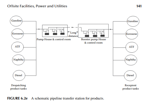
Though despatches of crude oil, petroleum, and petrochemical products are carried out by rail, road, and sea, a large quantity of these are transported through pipelines. Products like petrol, kerosene, ATF, HSD, and naphtha are transported through the same pipeline in batches (known as parcels) where each parcel of product is separated by the parcels of other products in sequence. For example, gasoline is transferred with naphtha parcels preceding the gasoline parcel at the upstream and following the gasoline parcel at the downstream. Similarly, kerosene parcels precede and follow ATF parcels; kerosene also precedes and follows HSD parcels as well. The sequence is maintained for continuous pumping operation for a single or multiple products in the same pipeline and without any break. In fact, interfacing plugs of two products are formed and can be drawn off following programmed timing and pressure maintenance. The above sequence is also helpful to dispose of mixed products in small quantities, which can be routed to a fi nished tank with a minimum adjustable specifi cation, e.g., a kerosene–diesel mixture can be upgraded as kerosene or diesel. Separate pipelines are earmarked for liquifi ed natural gas (LNG), crude oil, lubricating oil, etc. However, to maintain very high quality and to reduce intermittent operations, hard rubber ball separators (known as pigs) are introduced into the pipe to separate the products of different qualities. Of course, pig operations requires high cost of operation and maintenance, initial investment cost is much cheaper than the cost of construction of separate pipe line for each product. These are practiced for the same pipeline. In order to maintain uniform pressure and fl ow, booster pumping stations are provided at various suitable distant locations. Pipeline transfer is the most economic as compared to other modes of transport because of continuous transport in large quantities and the shortest delivery time. Sub-sea pipelines are the biggest means of transport of liquids and gases from the offshore producing wells to onshore storages. A pipeline transport mechanism is explained schematically in Figure 6.2e.
6.3.9 EFFLUENT WATER TREATMENT
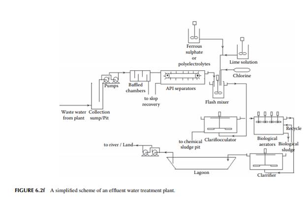
A refi nery or a petrochemical plant consumes huge amounts of water for processing, steam raising, cooling, fi re fi ghting, washing, etc. The water consumed is groundwater, river water, or sea water. Since sea water is saline, it can only be used after desalination. Ground and river water are usually sweet and require softening or demineralisation before use. Used water from a refi nery or petrochemical plant is contaminated with the hydrocarbon oils, acids, alkali, salts, and chemicals used. This contaminated water (waste water) is hazardous to plants, vegetation, and aquatic animals, and makes natural water unfi t for consumption. Hence, waste water must be treated within the refi nery or petrochemical plant to recover or remove a substantial amount of the contaminants before discharging to surrounding land or actuaries. A modern ETP involves three types of treatment—physical, chemical, and biological. In the physical treatment step, most of the oils and suspended matter are separated by gravity settling, API chain-grate separation, skimming operation, packed plate separation, dissolved air fl oatation, etc. Oil collected from these steps is known as slop, which is usually reprocessed along with crude oil. Following physical treatment, chemicals such as ferrous sulfate, lime, fuller’s earth, or, recently, poly-electrolytes are mixed in a high-speed mixer and later
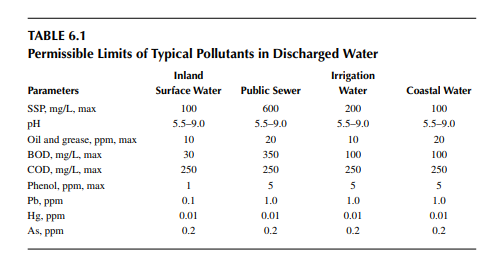
fl occulate the remaining oil and fi ne particles to settle by gravity. Physical and chemical treatments are also known as primary treatment. Biological treatment is known as secondary treatment. After primary treatment, dissolved oil and organic matter and salts are treated in a biological treatment unit. A modern biological treatment unit consists of a variety of units, such as the trickle bed fi lter, aerator, and lagoon. In the biological treatment step, dissolved oil and organic matter are converted to innocuous carbon dioxide by microbial organisms (microbes), which eat these oil and organic matter dissolved in water. The mass of microbes grown are later disposed of as fertiliser, land fi ll or incinerated in a furnace. Treated water is then stored in a separate lake to monitor the quality as per the specifi cations laid down by the pollution control board of the country before discharge to land or water resources. In some plants, attempts are being made to reuse the treated water for processing and even steam raising for the boilers, and little or no water is discharged outside the plant. For this zero discharge policy, tertiary treatment of effl uent using reverse osmosis, membrane separation, electrodialyses, ozonation, etc., are carried out to make the water suitable for reuse. A modern ETP is presented in Figure 6.2f. The permissible limits of pollutants in discharged water are presented in Table 6.1.
6.3.10 OFF GAS TREATMENT
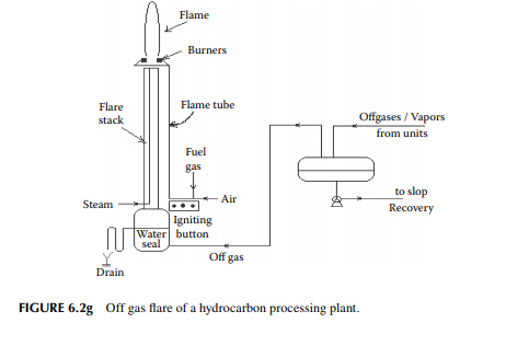
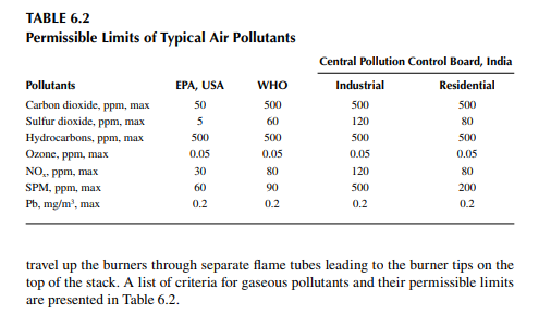
Gaseous effl uents or off gases containing hydrocarbon gases, such as methane, ethane, ethylene, propylene, and butane, along with hydrogen sulfi de, mercaptans, hydrogen, etc., in various proportions need to be exhausted to atmosphere for processing corrections, sudden safety releases, storage limitations, accidental release, etc. These off gases are burnt in furnaces for heat generation and excess gases are exhausted and burnt through a fl aring stack. The presence of sulfur compounds, usually
hydrogen sulfi de, which is a foul-smelling pollutant, are also burnt through a fl aring stack. Since fl ared off gases produce carbon monoxide (CO, for incomplete combustion), oxides of sulfur (SOx) and nitrogen (NOx), which are major pollutants of natural air, steps are taken by the refi ners or petrochemicals manufacturers to abate such pollution. Sulfur recovery from sulfur compounds and oxides has become a modern practice. Catalytic oxidation of hydrocarbons is also practised for complete combustion of hydrocarbons to reduce CO generation. A common fl are stack is shown in Figure 6.2g. Off gases are separated from the condensates and liquids in a drum before the gases enter the fl are stack. Gases are then burnt at the top of the stack. Burners at the top are kept lit by a fl ame produced by electrically sparking a mixture of butane or propane and air at the bottom of the stack. The generated fl ame fronts
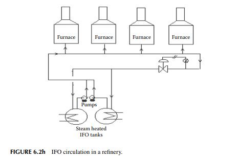
6.3.11 INTERNAL FUEL OIL CIRCULATION
Another important operation for any plant is the continuous supply of fuel to all the furnaces. Usually, in refi neries and petrochemical plants, off gases such as methane, ethane, propane, butane, olefi nic gases, and hydrogen are continuously produced. The excess of off gases during production is directly routed to the furnaces and the rest is fl ared for want of storage space. Liquid hydrocarbons, such as FO, asphalt, and wax, are also used as IFO, when off gases are not available in suffi cient quantities. Most modern furnaces are provided with combination fi ring, i.e., either or both gas and liquid fuels can be burnt in these furnaces. IFO storage and circulation is a part of the offsite facilities. Since IFO is a mixture of low-valued hydrocarbons, such as asphalt, short residue, vis-broken heavy distillates, and wax, the viscosity and melting point are high. Hence, steam-heating facilities are provided for storage tanks, and pipelines are also wound with steam coils (steam traced) to avoid congealing of the fuel oil. Positive displacement pumps, e.g., gear, screw, or lobe pumps, are employed to handle these viscous oils. To maintain constant pressure, it is essential to have a circulation circuit with a back pressure control arrangement. This is explained in Figure 6.2h.
6.4 POWER AND STEAM GENERATING PLANT
Since power consumption is enormous in refi neries and petrochemical plants, it is essential that these plants should have captive power plants. Usually, unwanted or excess hydrocarbons, both gas and liquid (known as internal fuel), are burnt in the power plant furnaces to raise steam for both electricity generation and for process steam requirements. A water tube boiler is used to raise high-pressure superheated steam for turning turbines to generate electricity. Demineralised water from
fi re box immediately after combustion. Superheated steam then enters the turbine and turns it at high speed. This is summarised below. 1. Hot water from the economiser enters the furnace tubes and then to the boiler drum where steam is separated from the condensates. 2. Steam from the boiler drum then enters the cyclone separators to evolve dry saturated steam and the condensates enter the mud drum where thermosifon takes place by natural convection currents due to the density difference between the condensates and the mud drum temperature. Dry saturated steam from the steam drum then enters the superheater section of the furnace to yield high pressure and high temperature superheated steam (usually above 65 bar and at 400°C). 3. Superheated steam then enters the turbine blades to generate mechanical rotation by converting the pressure energy into kinetic energy. As a result, moderate pressure steam is wasted from the turbine and is fi nally condensed. The turbine then turns the alternator for conversion of kinetic energy into electricity. Figure 6.3 depicts a typical power plant where hot gas is generated at the fi re box by burning fuel and the dry saturated steam is superheated. Hot fl ue gas then fl ows countercurrently with steam from the boiler drum, where water in the drum is reheated in the bottom drum and circulates back to the drum. Water concentrated with salts and other inorganic matter accumulates in the mud drum and water concentrated with salt is drained (blown) out time to time from the mud drum. Flue gas is then further cooled by the incoming feed water in the
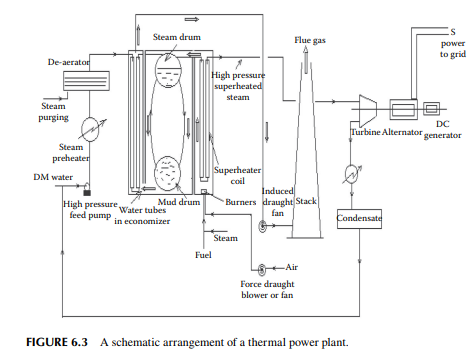
economiser section and fi nally leaves through the stack. The draught for the fl ue gas fl ow in the furnace is maintained by a combined force draught (FD) and induced draught (ID) fans. Water is converted to superheated steam, which then moves the turbine at high speed. Steam exhausted from the turbine is cooled and the condensate collected is reused in the boiler. The turbine shaft drives an alternator to produce power of alternating current and voltage, which is then transmitted to the transmission grid for distribution and consumption. A generator connected to the system supplies direct current to the poles of the alternator. However, steam is generated in a larger quantity than is required for power generation, such that the excess could be used as process steam and for steamdriven pumps/compressors in the plant. Electricity is consumed by pumping, compressing, and driving various rotary machines, electronic instruments and gadgets, lighting, etc. Medium- and low-pressure steam is also generated from high-pressure steam from the boiler through steam-reducing stations by means of bleeding steam to the atmosphere through nozzles. Some of the rotary machines are driven by steam in case of a power shutdown.
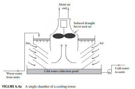
6.5 COOLING TOWER
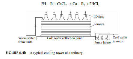
A large circulation of cooling water is required to condense and cool various streams of vapours, steam, gases, and liquids. Usually, the coolant water temperature is around 33°C and the exit hot water temperature from the coolers/condensers is around 50°C. This hot water is cooled by partial vaporisation of the water in a tower, known as a cooling tower, where hot water falls countercurrently against the rising air through wooden chambers. The hot water is distributed over the top chamber before falling down to the chambers. Each chamber has a fan to suck air from the chamber from the top this maintains induced draught (ID) to allow air to vaporise falling water and extract the vapour–air mix to atmosphere. Cold water is collected in a pond below the tower from where it is pumped back to the coolers and condensers. Such an arrangement of a tower chamber is shown in Figure 6.4a. While the demand for quantities of such cooling water is large, a number of chambers are provided. High pressure and high capacity pumps are used to maintain circulation through all the condensers and coolers in the plant. A typical cooling tower containing six chambers is shown in Figure 6.4b. Modern cooling towers use fi bre-reinforced plastic (FRP) louvres in place of wood.
6.6 WATER CONDITIONING PLANT
Raw water from river or ground is not suitable as such for boiler or processing purposes as it contains suspended and dissolved matter, hence the treatment of water is essential. Water is classifi ed as hard or soft, containing non-carbonate salts of magnesium, calcium, etc., other than sodium. Water containing carbonate salts can be removed by heating and hardness is termed temporary. Non-carbonates, such as chlorides and sulfates, cannot be removed by heating and that is why they lead to
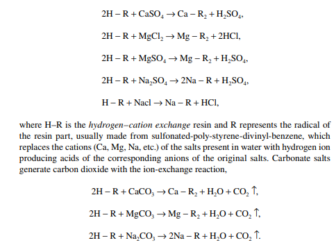
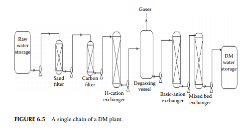
permanent hardness which is softened by using chemicals only like lime and soda. The hardness of water is expressed in terms of calcium carbonate precipitated equivalent to the salts present in the sample water. The presence of these salts gives rise to scale deposition in the equipment, causing damage to the surface due to corrosion and erosion, and the germination of fungi or algae, etc. Scale formation also causes a reduction in the heat transfer effi ciency of heat exchangers. Modern methods employ sand fi ltration followed by ion-exchange not only for the removal of suspended matter and salts, but also for deionising all the cations and anions producing pure water molecules. A major consumer of deminearalised (DM) water is the boiler, which requires very pure water without ions causing salts. Even dissolved oxygen is not allowed in the boiler feed water. The modern DM plant consists of ion-exchange resin-packed vessels. These resins are capable of replacing the calcium and magnesium ions with hydrogen ions by the following exchange reactions,
QUESTIONS
1. Sketch a conceptual layout of a refi nery having atmospheric and vacuum distillation units, a gas plant, a naphtha reforming unit with a naphtha pretreatment unit, off site, and an offi ce building.
2. Draw a layout of a naphtha cracking unit for olefi n manufacture showing the necessary off sites and other essential service centres.
3. Defi ne the terms battery limit, tank farm, and utilities.
4. Why does boiler feed water need treatment?
5. Briefl y describe the steam raising process in a boiler for power production.
6. Describe the principle of water cooling in a cooling tower.
7. Defi ne hardness of water and its measuring unit. Describe in brief the process of DM water production.
8. How are fuel gas and fuel oil distributions carried out in a refi nery?
9. Why does waste water need treatment?
10. How should off gases from a refi nery or a petrochemical plant be treated?