Imaging Systems
Thermal imaging instruments measure radiated infrared energy and convert the data to corresponding maps of temperatures. A true thermal image is a gray scale image with hot items shown in white and cold items in black. Temperatures between the two extremes are shown as gradients of gray. Some thermal imagers have the ability to add color, which is artificially generated by the camera’s video enhancement electronics, based upon the thermal attributes seen by the camera. Some instruments provide temperature data at each image pixel. Cursors can be positioned on each point, and the corresponding temperature is read out on the screen or display. Images may be digitized, stored, manipulated, processed and printed out. Industry-standard image formats, such as the tagged image file format (TIFF), permit files to work with a wide array of commercially available software packages.
Images are produced either by scanning a detector (or group of detectors) or by using with focal plane array. A scanning system in its simplest form could involve a single element detector scanning along each line in the frame (serial scanning). In practice, this would require very high scan speeds, so a series of elements are commonly scanned as a block, along each line. The use of multiple elements eases the scan speed requirement, but the scan speed and channel bandwidth requirements are still high. Multiple element scans do, however, result in a high degree of uniformity. The frame movement can be provided by frame scanning optics (using mirrors) or in the case of line scan type imagers, by the movement of the imager itself. Another method is to use a number of elements scanning in parallel (parallel scanning). These scanners have one element per line and scan several lines simultaneously. Scan speeds are lower but this method can give rise to poor image uniformity.
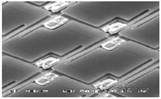
Another way thermal images are produced is with focal plane arrays (FPA), which are also known as staring arrays. A focal plane array is a group of sensor elements organized into a rectangular grid. A high magnification image of a portion of a mirobolometer focal plane array is shown to the right. The entire scene is focused on the array, each element cell then provides an output dependent upon the infrared radiation falling upon it. The spatial resolution of the image is determined by the number of pixels of the detector array. Common formats for commercial infrared detectors are 320 by 240 pixels (320 columns, 240 rows), and 640 by 480. The latter format is nearly the resolution obtained by a standard TV. Spatial resolution, the ability to measure temperatures on small areas, can be as fine as 15 microns. Temperature resolution, the ability to measure small temperature differences, can be as fine as 0.1° C.
The advantage of FPAs is that no moving mechanical parts are needed and that the detector sensitivity and speed can both be slower. The drawback is that the detector array is more complicated to fabricate and manufacturing costs are higher. However, improvements in semiconductor fabrication practices are driving the cost down and the general trend is that infrared camera systems will be based on FPAs, except for special applications. A microbolometer is the latest type of thermal imaging FPA, and consists of materials that measure heat by changing resistance at each pixel. The most common microbolometer material is vanadium oxide (VOX). Amorphous silicon is another relatively new microbolometer material.
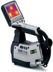
Applications extend from microelectronic levels to scanning wide areas of the earth from space. Airborne systems can be used to see through smoke in forest fires. Portable, hand-held units can be used for equipment monitoring in preventative maintenance and flaw detection in nondestructive testing programs.
Equipment for Establishing Heat Flow
In some inspection applications, such as corrosion or flaw detection, the components being inspected may be at ambient temperature and heat flow must be created. This can be accomplished by a variety of means. Heating can be accomplished by placing the part in a warm environment, such as a furnace, or directing heat on the surface with a heat gun or with flash lamps. Alternately, cooling can be accomplished by placing the component in a cold environment or cooling the surface with a spray of cold liquid or gas.
Image Capturing and Analysis
IR cameras alone or used with an external heat source can often detect large, near-surface flaws. However, repeatable, quantifiable detection of deeper, subtler features requires the additional sensitivity of a sophisticated computerized system. In these systems, a computer is used to capture a number of time sequence images which can be stepped through or viewed as a movie to evaluate the thermal changes in an object as a function of time. This technique is often referred to as thermal wave imaging.
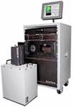
The image to the right shows a pulsed thermography system. This system uses a closely controlled burst of thermal energy from a xenon flash lamp to heat the surface. The dissipation of heat is then tracked using a high speed thermal imaging camera. The camera sits on top of the gray box in the foreground. The gray box houses the xenon flash lamp and it is held against the surface being inspected. The equipment was designed to inspect the fuselage skins of aircraft for corrosion damage and can make quantitative measurements of material loss. It has also been shown to detect areas of water incursion in composites and areas where bonded structure have separated.
Image Interpretation
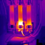
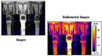
Most thermal imagers produce a video output in which white indicates areas of maximum radiated energy and black indicates areas of lower radiation. The gray scale image contains the maximum amount of information. However, in order to ease general interpretation and facilitate subsequent presentation, the thermal image can be artificially colorized. This is achieved by allocating desired colors to blocks of grey levels to produce the familiar colorized images. This enables easier image interpretation to the untrained observer. Additionally, by choosing the correct colorization palette the image may be enhanced to show particular energy levels in detail.
Many thermal imaging applications are qualitative in nature. The inspection simply involves comparing the temperatures at various locations within the field of view. The effects of the sun, shadows, moisture and subsurface detail must all be taken into account when interpreting the image, but this type of inspection is straightforward. However, great care must be exercised when using an infrared imager to make quantitative temperature measurements. As mentioned previously, the amount of infrared radiation emitted from a surface depends partly upon the emissivity of that surface. Accurate assessment of surface emissivity is required to acquire meaningful quantitative results.