Some thermal imaging techniques simply involve pointing a camera at a component and looking at areas of uneven heating or localized hot spots. The first two example applications discussed below fall into this category. For other applications, it may be necessary to generate heat flow within the component and/or evaluate heat flow as a function of time. A variety of thermal imaging techniques have been developed to provide the desired information. A few of these techniques are highlighted below.
Electrical and Mechanical System Inspection
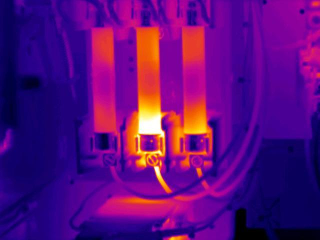
Electrical and mechanical systems are the backbone of many manufacturing operations. An unexpected shutdown of even a minor piece of equipment could have a major impact on production. Since nearly everything gets hot before it fails, thermal inspection is a valuable and cost-effective diagnostic tool with many industrial applications.

With the infrared camera, an inspector can see the change in temperature from the surrounding area, identify whether or not it is abnormal and predict the possible failure. Applications for infrared testing include locating loose electrical connections, failing transformers, improper bushing and bearing lubrication, overloaded motors or pumps, coupling misalignment, and other applications where a change in temperature will indicate an undesirable condition. Since typical electrical failures occur when there is a temperature rise of over 50°C, problems can be detected well in advance of a failure.
The image on the right above shows three electrical connections. The middle connection is hotter than the others. Connections can become hot if they are loose or if corrosion causes an increase in the electrical resistance.
Electronic Component Inspection

In electronics design and manufacturing, a key reliability factor is semiconductor junction temperature. During operation, a semiconductor generates heat and this heat will flow from the component. The heat will flow from the component in all directions, but will flow particularly well along thermally conductive connectors. This leads to an increase in temperature at the junctions where the semiconductor attaches to the board. Components with high junction temperatures typically have shorter life spans. Thermal imaging can be used to evaluate the dissipation of heat and measure the temperature at the junctions.
Corrosion Damage (Metal Thinning)

IR techniques can be used to detect material thinning of relatively thin structures since areas with different thermal masses with absorb and radiate heat at different rates. In relatively thin, thermally conductive materials, heat will be conducted away from the surface faster by thicker regions. By heating the surface and monitoring its cooling characteristics, a thickness map can be produced. Thin areas may be the result of corrosion damage on the backside of a structure which is normally not visible. The image to the right shows corrosion damage and disbonding of a tear strap/stringer on the inside surface of an aircraft skin. This type of damage is costly to detect visually because a great deal of the interior of the aircraft must be disassembled. With IR techniques, the damage can be detected from the outside of the aircraft.
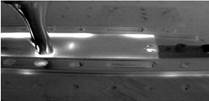
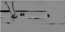
Flaw Detection
Infrared techniques can be used to detect flaws in materials or structures. The inspection technique monitors the flow of heat from the surface of a solid and this flow is affected by internal flaws such as disbonds, voids or inclusions. Sound material, a good weld, or a solid bond will see heat dissipate rapidly through the material, whereas a defect will retain the heat for longer.
A new technique call vibrothermography or thermosonic testing was recently introduced by researchers at Wayne State University for the detection of cracks. A solid sample is excited with bursts of high-energy, low-frequency acoustic energy. This causes frictional heating at the faces of any cracks present and hotspots are detected by an infrared camera.
Despite the apparent simplicity of the scheme, there are a number of experimental considerations that can complicate the implementation of the technique. Factors including acoustic horn location, horn-crack proximity, horn-sample coupling, and effective detection range all significantly affect the degree of excitation that occurs at a crack site for a given energy input.
Below are two images from an IR camera showing a 0.050″ thick 7075 aluminum plate sample with a prefabricated crack being inspected using a commercial vibrothermography system. The image on the left is the IR image with a pre-excitation image subtracted. A crack can be seen in the middle of the sample and just to the right of the ultrasonic horn. Also seen is heating due to the horn tip, friction at various clamping sites, and reflection from the hole at the right edge of the sample. The image on the right is the same data with image processing performed to make the crack indication easier to distinguish.