Abstract
Microwave Nondestructive Testing (MNDT) techniques have advantages over other NDT methods (such as radiography, ultrasonics, and eddy current) regarding low cost, good penetration in nonmetallic materials, good resolution and contactless feature of the microwave sensor (antenna). For MNDT techniques, the measured parameters are reflection coefficients, transmission coefficients, dielectric constants, loss factors, and complex permeabilities as a function of microwave frequency and temperature. These measured parameters can be related to material parameters of interest (e.g., flaws, binder content, moisture content, etc.) by suitable modeling and calibration. We have employed a free-space microwave measurement (FSMM) system which can measure electromagnetic properties (complex permittivity, complex permeability, reflection coefficients, etc.) for evaluation of composite materials. The main advantage of this FSMM system is that with suitable modifications, it is possible to make precise, accurate and reproducible MNDT measurements on composite materials under high or low temperature conditions and complex electromagnetic environmental conditions (e. g., DC biasing fields, ionizing radiation, etc.) due to contactless feature of free-space measurements. This measurement system consists of a pair of spot-focusing horn lens antennas, mode transitions, coaxial cables and a vector network analyzer (VNA). The inaccuracies in free-space measurements are due to two main sources of errors. 1) Diffraction effects at the edges of the material specimen. 2) Multiple reflection between horn lens antennas and mode transitions via the surface of the sample. The spot-focusing antennas are used for minimizing diffraction effects and free-space LRL (line, reflect, line) calibration method implemented on VNA eliminates errors due to multiple reflections. In this paper, we have used free-space implementation of reflection-transmission method for simultaneous determination of complex permittivity (e*) and complex permeability (m*) of magnetic materials. e* and m* values are reported for carbonyl iron loaded silicon rubber sheets with carbonyl iron concentration varying from 20% to 50 % (by volume).
Introduction
Microwave nondestructive testing (MNDT) of materials is an important science which involve development of sensors/probes, methods and calibration techniques for detection of flaws, cracks, defects, voids, inhomogeneities, moisture content (MC), etc. by means of microwaves [1]. They are increasing being used for quality control and condition assessment of concrete structures [2,3]. Recently, MNDT technique has been used for the measurement of slope-of-grain of timber for grading applications [4].
The term microwaves refer to alternating current signals/electromagnetic waves with frequencies between 300 MHz and 100 GHz. Since the penetration of microwaves in good conducting materials is very small, MNDT techniques are mainly used for nonmetallic materials. The spatial resolution of these techniques depends on the wavelength of the electromagnetic wave. For the microwave band of 3-100 GHz, wavelength varies from 100 mm to 3mm. These techniques have advantages over other NDE methods (such as radiography, ultrasonics and eddy current) regarding low cost, good penetration in nonmetallic materials, good resolution and contactless feature of the microwave sensor (antenna). Currently, microwave nondestructive testing can be best classified as a specialized technique (except for moisture gagging) as compared with other nondestructive test methods. But, modem electronics and computer processing will improve its potential for industrial applications [5].
For MNDT techniques, the measured parameters are reflection coefficients, transmission coefficients, dielectric constants, loss factors, and complex permeabilities as a function of frequency (microwaves) and temperature. These measured parameters can be related to material parameters of interest (e.g., flaws, inhomogeneities, moisture content, etc.) by suitable modeling and calibration. There are two classes of MNDT methods which are
1. free-space methods operating in the far-field region employing spot-focusing horn lens antennas and
2. waveguide methods operating in the near-field region which employ open-ended coaxial lines, rectangular waveguides, microstrip lines and cavity resonators as probes.
However, in the waveguide methods, it is necessary for the composite material to be in close contact with the probe. So, these methods are not contactless. In this paper, free-space methods are used which are non destructive as well as contactless.
We have developed a free-space microwave measurement (FSMM) system which can measure electromagnetic properties (complex permittivity, complex permeability, reflection coefficients, etc) for evaluation of composite materials. The main advantage of this FSMM system is that with suitable modifications, it is possible to make precise, accurate and reproducible MNDT measurements on materials under high or low temperature conditions and complex electromagnetic environmental conditions (e. g., DC biasing fields, ionizing radiation, etc) due to contactless feature of free-space measurements. Another significant advantage of free-space methods is that the measurements can be made when incident, reflected and transmitted signals are circularly/elliptically polarized electromagnetic waves. Composite materials such as timber which are lossy and anisotropic cause, a linearly polarized electromagnetic field to be depolarized (i. e. elliptically polarized) upon transmission through the material. So, MNDT techniques using free-space methods can be used for evaluation of these materials.
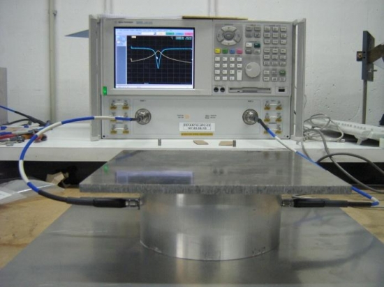
The FSMM system consists of a pair of spot-focusing horn lens antennas, mode transitions, coaxial cables and a vector network analyzer (VNA). The inaccuracies in free-space measurements are due to two main sources of errors.
3. Diffraction effects at the edges of the material specimen/sample.
4. Multiple reflection between horn lens antennas and mode transitions via the surface of the sample.
The spot-focusing antennas are used for minimizing diffraction effects and free-space LRL (line, reflect, line) calibration method implemented on VNA eliminates errors due to multiple reflections. The time domain gating or smoothing feature of VNA is used to reduce post calibration errors in reflection and transmission measurements.
R. M. Redheffer [6] was the first researcher to suggest a simple free-space method for measurement of dielectric constant from the measured phase of transmission coefficient. He reported that free-space methods are nondestructive and contactless techniques which are specially suited for dielectric measurement of materials. Harold L. Bassett [7] was the first researcher to measure complex permittivity in free-space using spot-focusing antennas at a frequency of 9.4 GHz. He measured complex permittivities of fused silica as a function of temperature from ambient to 2500° C. In the last twelve years, a number of free-space methods were developed for measurement of electromagnetic properties using FSMM system [8-10].
In this paper, we measured e* (= e‘– j e“) and m*(= m‘ -m“) values of carbonyl iron loaded silicon rubber (CISR) sheets using FSMM system in the frequency range of 8-12.5 GHz. These sheets have 20 % to 50 % concentration (by volume) of carbonyl iron powder in silicon rubber.
Free-space Microwave Measurement System
Fig. 1 gives a schematic diagram of the free-space microwave measurement system. A pair of spot-focusing horn lens antennas have been mounted on a large table (1.83 m ´ 1.83 m) of 2.54 cm thick wood. These antennas (model no. 857012X-950/C) were manufactured by Alpha Industries, Woburn, MA (USA). These antennas have two-equal plano-convex lenses mounted back to back in a conical horn antenna. One plano-convex lens gives an electromagnetic plane wave and the other plano-convex lens focuses the electromagnetic radiation at the focus. For these antennas, the ratio of focal distance to antenna diameter (F/D) of the lens is equal to one and D is approximately 30.5 cm.
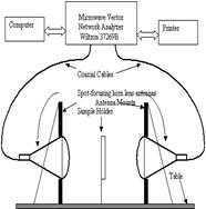 Fig 1: Free-space microwave measurement system for microwave non destructive testing of composite materials. Fig 1: Free-space microwave measurement system for microwave non destructive testing of composite materials. |
A specially fabricated sample holder is mounted at the common focal plane for holding planar samples. The sample is sandwiched between two perspex plates (one plate is fixed and the other is moveable). The transmit and receive horns are mounted on a carriage and the distance between them can be changed with an accuracy of 25.4 mm. by using a dial indicator. From measured radiation patterns supplied by the manufacturer, the 3 dB and 10 dB E-plane beamwidths can be calculated. These beam widths will vary in proportion to wavelength in free space wavelength (lo). The 3 dB and 10 dB beamwidths are approximately lo and 1.9 lo, respectively. The depth of focus for these horn lens antennas is approximately 10 lo . Because of spot focusing action of antennas at the focus, the diffraction effects are negligible if the minimum transverse dimension of the sample is three times the 3-dB E-plane beamwidth (which is approximately 3 lo). This measurement set up covers a frequency range of 8.0-14.0 GHz . But, the same setup can be used in the frequency range of 8.0 -40 GHz by appropriate change of mode transitions.
The focused antennas are connected to the two ports of the Wiltron 37269B vector network analyzer by using precision coaxial cables, rectangular-to-circular waveguide adapters and coaxial-to-rectangular waveguide adapters. The receive antenna can be rotated from co-polarized position in steps of 10° between – 70° to + 70° . The polarization of transmit and receive antennas depend on polarization of the wave in rectangular waveguide used in coaxial-to-rectangular waveguide adapter. Vector network analyzer measures amplitude and phase of reflected or transmitted signal in transmission media such as coaxial line, rectangular/circular waveguide, microstrip line and free-space. A complete VNA system consists of a fast sweeping synthesized signal source, auto-reversing S-parameter test set, display unit and a controlling computer. This network analyzer is used to make accurate reflection and transmission (S-parameters) measurements in free-space using line-reflect-line calibration model.
Because of multiple reflections between coaxial-to-rectangular waveguide adapters, rectangular-to-circular waveguide transitions and hom lens antennas, there is a need to calibrate the measurement system in free-space for S-parameter measurements. We have implemented free-space LRL calibration technique [8,9]. This calibration technique along with smoothing or time domain gating feature of the network analyzer, can eliminate effects of multiple reflections. It is known that LRL calibration technique can produce the highest quality calibration available. Also, it is easier to realize LRL calibration standards in free-space as compared with open, short and matched termination standards used in coaxial and waveguide media. So, LRL calibration is the best calibration technique for the free-space medium. Free-space LRL calibration is implemented in free-space by establishing three standards. The reference planes for port1 and port2 are located at the focal planes of transmit and receive antennas. The through standard is realized by keeping the distance between two antennas equal to twice the focal distance. It means that there is a common focal plane for the through standard. The line standard is achieved by separating the focal planes of the two antennas. The distance between focal planes is approximately a quarter wavelength at midband, The reflect standards for port 1 (transmit hom) and port 2 (receive hom) are obtained by placing a metal plate (15.24 cm ´ 15.24 cm ´ 2.1 mm) on sample holder at the reference plane.
LRL calibration kit for coaxial line of the vector network analyzer is modified by defining LRL standards regarding wave impedances and line lengths. Because of the characteristics of spot-focusing hom lens antennas, the electromagnetic fields in the neighborhood of common focal plane are plane wave in character, so the use of modified coaxial calibration kit is justified. The error model for LRL calibration includes error terms for directivity, isolation, source impedance match, load impedance match, transmission frequency response and reflection frequency response. This error model has 12 error coefficients which are evaluated from measured data for the LRL standards. By performing the LRL calibration using the free-space calibration standards, two-port free-space LRL calibration is obtained.
For measurement of complex reflection coefficient (S11), and complex transmission coefficient (S21) of composite material sample, the reference planes corresponding to transmit and receive antennas were located at the front and back face of the sample, respectively. The residual post calibration errors can be further reduced by using time domain gating or smoothing function of VNA. It is observed that magnitude and phase of S11 are within ± 0.2 dB and ± 1° of the theoretical value of 0 dB and 180° for the metal plate. For the through connection, the measured magnitude and phase of S21 are within ± 0.05 dB and ± 0.2° of the theoretical values of 0 dB and 0° .
Reflection-Transmission Method
In this method, complex permittivity and complex permeability of a planar sample of composite material, can be calculated from measured complex reflection coefficient (S11) and complex transmission coefficient (S21). This method is described in detail in reference 9. This method is especially suited for quick, routine and broadband measurement of e* and m* of high-loss materials. For thin and flexible samples such as CISR sheets, the accuracy of measurement of S11 and S21 is poor because of sagging of the sample when mounted on the sample holder [9]. So, the sample is sandwiched between two Teflon plates which are half-wavelength at mid-band. The actual values of S11 and S21 of sample are calculated from the measured S11 and S21 of Teflon-sample-Teflon plate assembly from the knowledge of the complex permittivity and thickness of the Teflon plates. In our research, the complex permittivity and thickness of Teflon is taken as 2.08 – j 0.00077 [9] and 11.2 mm, respectively. These Teflon sheets are half-wavelength at 9.2795 GHz. From the error analysis [9], it is observed that the accuracy in e‘ , e” , m‘ and m” are better than ± 5 %. If the dielectric loss tangent (e”/e‘) is less than 0.1. Then, e” can not be measured accurately. Also, if the magnetic loss tangent (m”/m‘ ) is less than 0.1. Then, m” can not be measured accurately.
Experimental Results
Carbonyl iron loaded silicon rubber (CISR) sheets are used as a lossy microwave materials for free-space microwave absorbers, EMI shielding applications, microwave attenuators and microwave terminations [11]. Carbonyl iron is a ferromagnetic material and so, CISR sheets are expected to have complex permeability other than 1.0 – j 0.0. Three CISR sheets were tested with carbonyl iron concentration varying from 20 % to 50 % by volume. These CISR sheets were manufactured by Emerson & Cuming Microwave Products, Inc., Randolph, MA, USA 02368. The thicknesses of CISR sheets with 20 %, 40 % and 50 % concentration of carbonyl iron powder, are 3.54 mm, 3.15 mm and 1.58 mm, respectively. e* and m* values of CISR sheets are measured in the frequency band of 8-12.5 GHz. Because errors due to smoothing function of VNA are large at the bandages, e* and m* values were calculated only in the frequency range 8.5-12 GHz. Tables 1, 2 and 3 give e* (= e‘ – j e”) and m* (= m‘ – m”) values for CISR sheets.
| Frequency(GHz) | e’ | e” | m’ | m” |
| 8.5 | 5.62 | 0.4 | 1.2 | 0.47 |
| 9.0 | 5.6 | 0.31 | 1.2 | 0.48 |
| 9.5 | 5.6 | 0.19 | 1.18 | 0.46 |
| 10.0 | 5.58 | 0.2 | 1.16 | 0.45 |
| 10.5 | 5.62 | 0.42 | 1.15 | 0.41 |
| 11.0 | 5.49 | 0.37 | 1.12 | 0.4 |
| 11.5 | 5.63 | 0.72 | 1.13 | 0.35 |
| 12.0 | 5.53 | 0.83 | 1.09 | 0.33 |
| Table 1: e* and m* values of CISR sheet with Silicon Rubber 80 % by volume and Carbonyl Iron 20 % by volume. |
| Frequency(GHz) | e’ | e” | m’ | m” |
| 8.5 | 15.6 | -0.48 | 1.81 | 1.83 |
| 9.0 | 15.46 | -0.52 | 1.75 | 1.81 |
| 9.5 | 15.16 | -0.53 | 1.66 | 1.80 |
| 10.0 | 15.04 | -0.51 | 1.60 | 1.79 |
| 10.5 | 14.92 | -0.35 | 1.57 | 1.79 |
| 11.0 | 14.86 | -0.23 | 1.54 | 1.80 |
| 11.5 | 14.87 | -0.09 | 1.52 | 1.80 |
| 12.0 | 14.93 | 0.02 | 1.50 | 1.79 |
| Table 2 :e* and m* values of CISR sheet with Silicon Rubber 60 % by volume and Carbonyl Iron 40 % by volume. |
| Frequency(GHz) | e’ | e” | m’ | m” |
| 8.5 | 17.5 | 0.43 | 1.64 | 2.13 |
| 9.0 | 17.19 | 0.17 | 1.62 | 2.12 |
| 9.5 | 16.7 | -0.33 | 1.53 | 2.07 |
| 10.0 | 16.4 | -0.36 | 1.47 | 2.08 |
| 10.5 | 16.22 | -0.10 | 1.42 | 2.04 |
| 11.0 | 15.64 | -0.04 | 1.30 | 2.05 |
| 11.5 | 15.86 | -0.01 | 1.33 | 2.0 |
| 12.0 | 15.39 | 0.03 | 1.23 | 2.01 |
| Table 3 :e* and m* values of CISR sheet with Silicon Rubber 50 % by volume and Carbonyl Iron 50 % by volume |
Conclusions
Microwave nondestructive testing using FSMM system is a contactless technique which can be implemented by measuring electrical parameters such as complex permittivity and complex permeability as a function of frequency and temperature. From tables 1 to 3, it is observed that values of e‘ and m” increase as the concentration of carbonyl iron powder increases from 20 % to 50 %. This is due to higher volume fraction of the magnetic material in the composite. Also, for 50 % concentration of carbonyl iron, there is a significant decrease in e‘ and m‘ with increasing frequency. Expected values of e” is greater than or equal to zero. The negative values of e” are due to measurement errors.Also, due to dielectric loss tangent being less than 0.1, e” can not be measured accurately. But, reflection-transmission method gives accurate values of e‘, m‘ and m” of CISR sheets.