
Ground penetrating radar operates by transmitting pulses of ultra-high frequency radio waves (microwave electromagnetic energy) down into the ground through a transducer (also called an antenna). The ground penetrating radar antenna (transducer) is pulled along the ground by hand or behind an ATV or a vehicle. The transmitted energy is reflected from various buried objects or distinct contacts between different earth materials. The antenna then receives the reflected waves and stores them in the digital control unit. The control unit registers the reflections against two-way travel time in nanoseconds and then amplifies the signals. The output signal voltage peaks are plotted on the ground penetrating radar profile as different colour bands by the digital control unit.


How Deep Can GPR Go Into the Ground?
The depth to which ground penetrating radar waves can reach beneath the ground surface is mainly dependent on two conditions: 1) the type of soil or rock in the GPR survey area, and 2) the frequency of the antenna used. Ground penetrating radar can reach depths of up to 100 feet (30 meters) in low conductivity materials such as dry sand or granite. Moist clays, shale, and other high conductivity materials, may attenuate or absorb GPR signals, greatly decreasing the depth of penetration to 3 feet (1 meter) or less.
The depth of penetration is also determined by the GPR antenna used. Antennas with low frequencies of from 100 to 200 MHz obtain subsurface reflections from deeper depths (about 25 to 100 feet or more), but have low resolution. These low frequency antennas are used for investigating the geology of a site, such as for locating sinkholes or fractures, and to locate large, deeply buried objects.
Antennas with higher frequencies of from 400 to 1,500 MHz obtain reflections from shallow depths (0 to about 14 feet), and have high resolution. These high frequency antennas are used to investigate surface soils and to locate small or large, shallow, buried objects, such as utilities, gravesites, and also rebar in concrete.
GeoModel, Inc. conducts ground penetrating radar surveys using a SIR-3000 digital control unit and various antennas with frequencies ranging from 100 to 1,500 MHz The Geo Model, Inc. principals have over 50 years of combined experience and conduct GPR surveys nationwide.
| Ground penetrating radar (GPR) is a tool for indirectly looking at underground objects (such as graves), gravel and sand layers, and other underground structures. The information or data received by GPR is like an x-ray or map of the underground. In fact, GPR uses electromagnetic (EM) waves, as x-ray machines do, but GPR uses radio waves, which have a longer wavelength (see Figure 1). The wavelength, or the length of one wave, is the fundamental difference between the forms of electromagnetic energy. For example, the wavelength of x-rays range from about 10 billionths of a meter to about 10 trillionths of a meter, whereas radio waves can be a few meters long.GPR antennaeTo collect GPR data, two antennae are repeatedly placed along the ground surface at a constant interval. Unlike a radio or TV antenna, GPR antennae usually look like two skis that vary in length from less than ½ meter long to 4 or more meters long as shown in Figure 2. Different length antennae send different frequency waves into the ground. Frequency is the number of wavelengths per second, measured in Hertz; radio waves are measured in millions of wavelengths per second, which is called megahertz (MHz). The wavelength for each antenna is approximately equal to the antenna length in most underground material. Figure 3 compares different frequency antennae and the waves they produce. The 200 MHz wave completes four wavelengths in the same amount of time that the 100 MHz wave completes two wavelengths, which is why 200 MHz has been designated as higher frequency. The higher frequency enables 200 MHz waves to pick up more layers, yielding higher resolution data. | 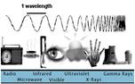 Figure 1. The electromagnetic spectrum, and the definition of a wavelength. Wavelengths become shorter as the spectrum moves from radio waves to gamma rays. (Modified on 9/21/98 from Figure 1. The electromagnetic spectrum, and the definition of a wavelength. Wavelengths become shorter as the spectrum moves from radio waves to gamma rays. (Modified on 9/21/98 from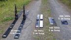 Figure 2. GPR antennae with frequencies and length labeled. Handles, transmitter, and receiver are on the 25 MHz antennae. (Photo by Brian Thayer.) Figure 2. GPR antennae with frequencies and length labeled. Handles, transmitter, and receiver are on the 25 MHz antennae. (Photo by Brian Thayer.)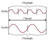 Figure 3. Higher frequency waves will complete wavelengths more often than lower frequency. Figure 3. Higher frequency waves will complete wavelengths more often than lower frequency. |
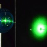
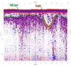
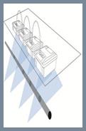
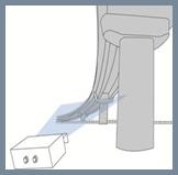
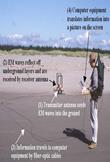 Figure 4. Each GPR trace involves the four steps outlined above. The steps take just a few seconds and the equipment is then moved along a path at a constant interval (the process requires a second person to move the antennae). (Photo courtesy of Harry Jol.) Figure 4. Each GPR trace involves the four steps outlined above. The steps take just a few seconds and the equipment is then moved along a path at a constant interval (the process requires a second person to move the antennae). (Photo courtesy of Harry Jol.)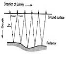 Figure 5. Illustration of the step-by-step GPR process showing how EM waves reflect off reflectors (layers) in the ground. (Modified from Jol and Smith, 1991. Ground penetrating radar of northern lacustrine deltas. Canadian Journal of Earth Sciences, 28, 1939-1947.) Figure 5. Illustration of the step-by-step GPR process showing how EM waves reflect off reflectors (layers) in the ground. (Modified from Jol and Smith, 1991. Ground penetrating radar of northern lacustrine deltas. Canadian Journal of Earth Sciences, 28, 1939-1947.)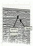 Figure 6. A GPR profile of a dune in North Carolina. Notice the continuity of the water table reflection. (Wenell and Havholm, unpublished data, 1998.) Figure 6. A GPR profile of a dune in North Carolina. Notice the continuity of the water table reflection. (Wenell and Havholm, unpublished data, 1998.) | The GPR processFigure 4 shows the GPR equipment ready for operation. The transmitter antenna begins the process by sending EM waves in to the ground. While in the ground, the EM waves are reflected off underground layers and objects, as illustrated in Figure 5. The receiver antenna receives the waves that reflect off the layers and measures the travel time and wave strength. The measurements are sent through fiber-optic cables to computer equipment that converts the measurements into an image like Figure 6, which is from a sand dune in North Carolina. Measurements are made at a constant interval for tens or hundreds of meters to ensure accurate representation of the area being examined.GPR applicationsGPR is applied in a variety of fields, from cemetery management to archeology to mining. Perhaps one of the most interesting applications of GPR was in Norway where seven victims of the 1918 Spanish Flu were buried; that flu is considered the deadliest virus that the world has ever known. What is unique about the graves in Norway is that the bodies are buried where a portion of the ground is permanently frozen and they are likely to be preserved as a result. A project planned to use GPR to determine the depth of the graves; if the graves were found to be below the active permafrost, the layer that thaws every summer, then the bodies would be worthy to study because the virus would probably be preserved as well. Because there have been reoccurrences of deadly flu viruses, scientists could use information found in the Norwegian graves to prevent the next outbreak (Gladwell, Malcolm. “The Dead Zone.” The New Yorker, Sept. 29, 1997).For more information on the Spanish Flu project, visit the following sites: |
 | Why GPR Technology?– GPR technology can locate any pipes / structures / objects: metallic and non-metallic (PVC, concrete, etc.)- GPR is non-destructive and non-invasive, revealing a wealth of internal detail without the need for coring or breaking out reducing associated risks and costs;- GPR complements the surface inspection with a documentable and precise (quan titatively interpretable) image of the underground. |
IDS evolved the concept of standard ground penetrating radar introducing the concept of multi-frequency, multi-channel ground penetrating systems.
Why use an array of antennas?
– High Quality: the close spacing of the antennas enable an accurate and homogenous 3D reconstruction of the subsurface giving to the user the ability to see shape and size of buried objects.
– Productivity: using more antennas combined with positioning system can save time in the field; to accurately reconstruct the path of the underground in complex situations;
– Safety: array solution can be towed by vehicles, no need of time consuming and dangerous field surveys on roads.
IDS GPR Products Offering: Aladdin, Opera Duo, RIS Hi-BrigHT, RIS Hi-Pave, RIS MF Hi-Mod, RIS One & RIS Plus, SRS SafeRail System, Stream EM, Stream X.
2. Interferometric Radar
Monitoring structure movements and vibrations (bridges, buildings, dams, historical monuments, towers etc.) and ground movements (mine walls, landslides, glaciers, land subsidence…) is an increasingly important task for today’s construction and geotechnical engineers.
IDS Interferometric Radar Solutions are developed to make it easy.
IDS Interferometric radar solutions, embodied by the IBIS range of products, provide innovative and unique solutions for remote, long range, continuous real-time inspection of the above mentioned areas, spanning from structures to geological environments, by measuring the phase difference of reflected waves to provide a detailed image of all displacements.
Remote sensing, displacement accuracy, real-time one-dimensional simultaneous mapping of all displacement detected on the structure, fast installation and operation,