Introduction
During the last decade, the interest in research of mechanical behavior of ultrafine-grained (UFG) and nanostructured (NS) metal alloys has been risen sharply [1–13]. Compared to their coarse-grained counterparts, UFG and NS metals exhibit significantly higher static yield strength, hardness, but lower tensile elongation. Ultrafine-grained materials produced by severe plastic deformation (SPD) methods exhibit a high strength, good damping properties, and superplastic properties over a limited range of strain rates at high temperatures. The increase of UFG material strength can be explained on the behavior of dislocation at submicrometer grain size. Laws of plastic deformation operating at room temperature for coarse-grained metals usually are based on dislocation mechanisms [1–9]. When grain size is decreased in nanometer range, dislocation activity becomes difficult. Therefore, plastic deformation resulting to dislocation nucleation and motion limits ductility of NS and UFG materials. Strain rate sensitivity of flow stress also depends on grain size [9–11].
Similarity of mechanical behavior of materials in wide range of loading conditions takes place for metals combining into several groups [14]. Metal alloys with face-centered cubic (FCC), body-centered cubic (BCC), and hexagonal close-packed (HCP) crystalline lattices can be related to three groups. Mechanical behavior of these groups of metals has to be described by various constitutive models [2–4]. We can expect that UFG metals with FCC, BCC, and HCP lattices will have various laws of plastic deformation at high strain rates also.
Mechanical behavior of NS and UFG materials under shock wave loading requires understanding of fundamental laws of the deformation and failure mechanisms at high strain rates.
Mechanical behavior of nanostructured and ultrafine-grained metal alloys
Important information about mechanical behavior of nanostructured and ultrafine-grained materials under dynamic loading is contained in the experimental data on high-speed interaction of plates; results of tests on compression and tension by using a split-Hopkinson pressure bar (SHPB), also known as Kolsky bar test; and results of tests using high-rate servo-hydraulic machine Instron VHS.
Experimental results obtained from the tests of metals and alloys by these methods showed that the patterns of deformation in ultrafine-grained and coarse-grained materials are different not only under quasi-static but also intense dynamic loading.
The free surface profiles of shock wave in the UFG Ti-6Al-2Sn-2Zr-2Mo-Si titanium alloy are shown in Figure 1.

The metal plate was loaded with shock pulses, which were obtained by the impact of thin aluminum. The metal plate was loaded with shock pulses, which were obtained at impact thin aluminum plates at a speed of 650 ± m/s [13, 15].
The movement of the back surface of the plates when exposed to a shock pulse was recorded using a laser Doppler interferometer VISAR with subnanosecond time resolution [15].
Shock wave in UFG alloys has the two-wave structure as in CG alloys. The shock wave in the UFG alloys has a double structure in coarse-grained alloys. Elastic precursor propagates with the longitudinal sound speed. The bulk compression wave or the plastic wave propagates through compressed material with the bulk speed of sound.
Curves 1 and 2 correspond to specimens with grain size ~300 nm, and the Curve 3 corresponds to coarse-grained specimen with grain size of 20 μm [13, 15]. The thicknesses of UFG specimens 1 and 2 were 0.835 and 6.36 mm, respectively. The thickness of coarse-grained specimen was 10 mm.
The Hugoniot elastic limit (HEL) (dynamic elastic limit) for an elastic plastic material can be calculated by the formula [15, 16]

where σHEL is the Hugoniot elastic limit, ρ0 is the initial mass density, CL is the longitudinal speed of sound, and upHEL = ufsHEL/2 is the maximum particle velocity in the elastic precursor.
The average strain rate in the elastic precursor is measured by the ratio [16]

where ΔtHEL is a time, which is achieved by the amplitude of the elastic precursor.
The calculated ratio of the bulk modulus of nanostructured titanium to the bulk modulus of coarse-grained titanium agrees with experimental data. Sound velocities of materials can be calculated by relations [16]

where Cs, Cb, CL are the shear, bulk, and longitudinal sound velocities; B is the bulk modulus; and μ is the shear modulus.
The effective bulk modulus B of nanostructured material can be determined by the equation

where B(c) is the isentropic bulk modulus of a crystalline phase; B(g) ≈ 0.45B(c) and B(tj) ≈ 0. 5B(c) are the bulk modulus of a grain boundary phase and the bulk modulus of material near the triple junctions correspondingly; and C(c), C(g), and C(tj) are the volume fractions of these phases correspondingly.
The volume fraction of the triple junction and the volume fraction of grain boundaries were described by the equations

where dg is the grain size; b is the modulus of the Burgers vector; and β(g), β(tj), α(g), and α(tj) are the constants of a material.
The values of C(g) and C(tj) versus grain size are shown in Figure 2.

As the grain size is decreased into the nanometer range (<100 nm), the volume of grain interfaces sufficiently increased. The calculated ratio of the bulk modulus of nanostructured materials to the bulk modulus of coarse-grained materials is demonstrated in Figure 2.
From Eqs. (3)–(6), it follows that the longitudinal and bulk sound velocities for the UFG and CG alloys differ insignificantly. Thus, in the absence of pores and microcracks, UFG and CG alloys have close values of mass density, elastic moduli, and sound velocities Cs, Cb, and CL.
The dynamic yield stress of the material σy acting on the shock adiabat is determined by the formula [15, 16]

where ν is Poisson’s ratio.
The experimental results in Figure 1 showed that the UFG and CG titanium alloys have similar amplitude values of the elastic precursors at the equivalent distances to the free surface of the samples. Thus, the Hugoniot elastic limits of UFG and CG titanium alloys can be the same. But the quasi-static yield strength of titanium alloys depends on grain size in accordance with the Hall-Petch relation, as shown in Figure 3.

Filled symbols show experimental data for titanium alloys [13, 18] and magnesium alloys [7, 8, 19].
Experimental investigations indicate that the prevailing deformation mechanisms are changed for the grain size below ~100 nm. The Hall-Petch relation (Eq. (8)) is satisfied for many polycrystalline materials, but the values of coefficients σ0 and k are changed at the grain size about several hundred nm (range UFG) and 30–20 nm (range NS) as shown in Figure 3. Filled symbols show experimental data for titanium alloys [13, 18] and magnesium alloys [7, 8, 19]:

where σ0 is the yield strength, dg is the grain size, σ0, and k are the material constants.
Figure 4 shows shock wave profiles in UFG and CG copper specimens [15, 20, 21]. Copper refers to isomechanical group of materials with the FCC lattice [15]. Curve 1 corresponds to UFG structure of specimen with grain size of ~500 nm. Curve 2 is received for a material in which fine grains occupied only 85% of volume. These experimental results testify that the Hugoniot elastic limit (HEL) and the spall strength (σsp) of copper sharply decrease with the decrease of the relative volume occupied with UFG structure.
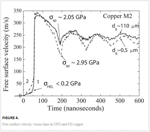
The solid Curve 1 corresponds to CG specimen, and dashed Curve 2 corresponds to UFG specimen. The HEL of UFG copper M2 (~0.4 GPa) is about twice that of polycrystalline alloy.
Precipitate-strengthened aluminum, magnesium alloys, copper, and some other metals possess a high strength and ductility. The presence of nanoparticles and precipitate phases influences on the yield stress and the spall strength of UFG alloys under shock wave loadings.
In Figure 5, shock wave profiles in precipitate-strengthened aluminum alloy AA6063T6-AlMg0.5Si0.4are shown [6].
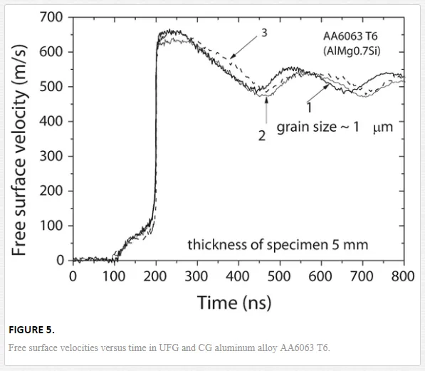
Curves 1, 2, and 3 correspond to AA6063T6 alloy after two and eight passes of equal-channel angular pressing (ECAP) and without ECAP, respectively. Coarse-grained alloy specimens had a grain size of ~100 μm. UFG structure was created by repeated ABC ECAP passes. Nanoparticles of Mg2Si were formed by means of thermal treatment of alloy before ECAP treatment. The HEL of coarse-grained AA6063T6 was equal to ~0.33 GPa, and the spall strength was equal to ~1.29 GPa, whereas the HEL values of UFG alloy were ~5.7% higher (~0.35 GPa), and the spall strength was equal to ~1.48 GPa. Thus, the spall strength and the yield strength of UFG alloys depend not only on grain size but also on concentration and sizes of phase precipitates.
The Hugoniot elastic limit of ultrafine-grained metal alloys and their coarse-grained counterparts is not significantly different. The rate of elastic precursor attenuation is above in UFG alloys, than in coarse-grained counterparts.
The tensile strength at high strain rate can be determined from the analysis of shock wave profiles shown in Figures 1, 4, and 5. These values correspond to the spall strength. The spall strength is determined by formulas [15, 16]

where σsp is the spall strength; ρ0 is the initial mass density; Cb is the bulk speed of sound in the shock-compressed material; Δufs is the difference between the maximum speed of the free surface of the target and speed in front of the spall pulse; δ is the amendment, to account for the velocity gradients at the free surface in front of spall pulse and in the front; h is the thickness of the target; CL is the longitudinal sound velocity; and u˙1u˙1 is the change in the free surface velocity in time in front of the spall pulse.
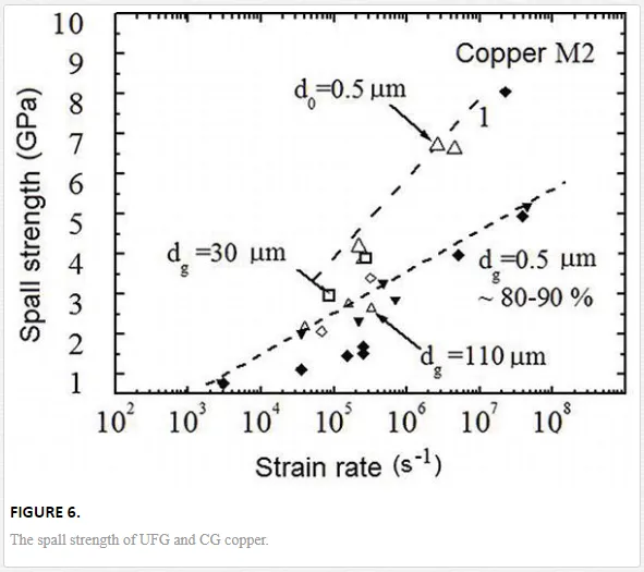
The spall strength σsp of copper specimen with grain size of 500 nm is ~2.95 GPa, whereas the spall strength of specimen with grain size of 100 μm is only ~ 2.05 GPa. The spall strength of UFG and CG copper is shown in Figure 6.
The spall strength of UFG and CG and single crystal aluminum alloys is shown in Figure 7.
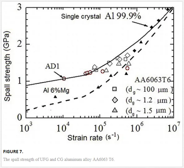
Filled symbols show experimental data for Al single crystal [15], AD1 [15], AMg6 [15], and AA6063T6 [6].
These results correlate with data on the increasing of the quasi-static yield stress of FCC metals at a decrease of grain sizes (Figure 8). Experimental data [4–6, 18, 20, 21] for copper and aluminum alloys are shown by the filled symbols.
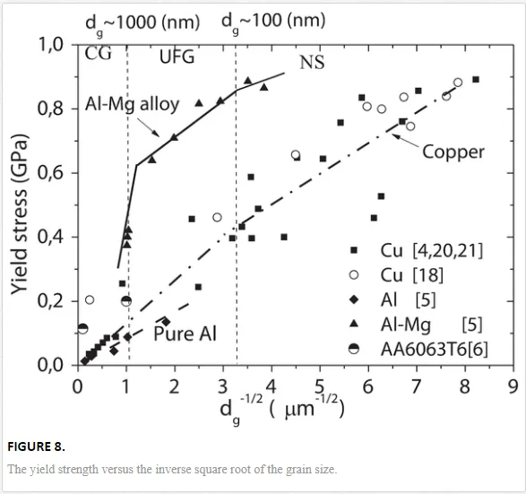
Changes of curve slope both FCC and HCP metal alloys (Figures 3 and 8) testify to peculiarities of the mechanical behavior of UFG alloys when the grain size varied from 1000 to ~10 nm.
Bulk UFG alloys usually have a dispersion of grain size appearing at their manufacturing by severe plastic deformation (SPD) methods. A specific volume, which is occupied with UFG structure, influences on the HEL and the spall strength of alloys.
Dissipation of mechanical energy during deformation of ultrafine-grained and coarse-grained titanium and zirconium alloys
Research of deformation localization and fracture mechanisms of NS and UFG alloys was investigated by a combination of structure-sensitive methods [1, 2, 22–27]. The high sensitivity of modern infrared (IR) thermal vision systems in combination with the opportunity of noncontact continuous temperature and strain measurements gives us important information on processes of damage and fracture. Recently, it has been shown that UFG titanium has a peak of an internal friction at temperatures of 450–500°C, which results from the processes of recovery and recrystallization [22]. Experimental data were obtained about the deformation and thermal characteristics of the UFG and CG VT1-0 alpha titanium alloy and E110 zirconium alloy [26–28]. The mechanical tests were performed by means of servo-hydraulic machine Instron VHS 40/50–20. These specimens were nanostructured by means of a combined method of severe plastic deformation (SPD).
The residual stresses in the specimens were relieved by means of annealing. Samples from UFG titanium and zirconium were converted to coarse grain using a high-temperature annealing. The forces were registered by the sensor DYNACELL with accuracy up to 0.2%.
The obtained curves of true stress—true strain were used for determination of the yield strength, the strength, and the strain to failure. The temperature distributions on the specimen surface under tension with constant strain rate were registered by using the FLIR system SC7700M series infrared camera.
IR thermograms were registered with maximum recording frequency of 115 Hz. The resolution was ~20 micron and the image format is of 640 × 512 mm.
The thermal camera was at a distance of 0.4 m from the specimen. The software of the FLIR system SC7700M was used for interpretation of the registered data [24]. The reflection surface of the samples was close to the “absolutely black body” through the use of carbon blackening.
The thermal vision system allowed one to record not only the specimen’s surface temperature distribution but also the current dimensions of specimen during the deformation. The specimen size, the loading force, and the loading times were recorded in the process of quasi-static tensile tests. Engineering true stress, strain, and true strain were calculated using recorded data.
True stress-strain curves of coarse-grained VT1-0 titanium and E110 zirconium specimens under tension are shown in Figures 9 and 10, respectively. True stress-true strain curves are marked as Curve 1. Curve 2 corresponds to the engineering stress and strain diagrams. Figures 9 and 10 also showed the temperature distribution on the surface of the samples for several increasing strains.
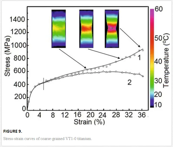
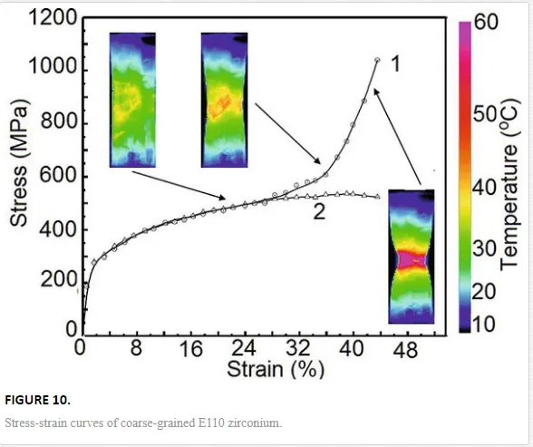
Temperature change is caused by dissipation of mechanical energy during plastic deformation.
The stress-strain curve has a parabolic ascending branch, which passes into the descending portion having a negative coefficient of strain hardening. True stress-strain diagrams of UFG VT1-0 titanium and E110 zirconium specimens under tension are shown in Figures 11 and 12, respectively.
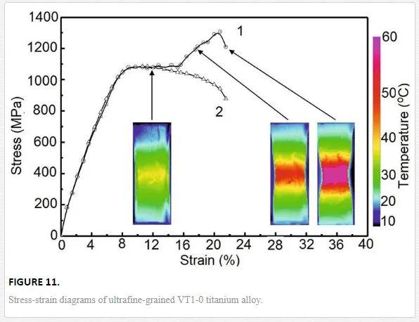
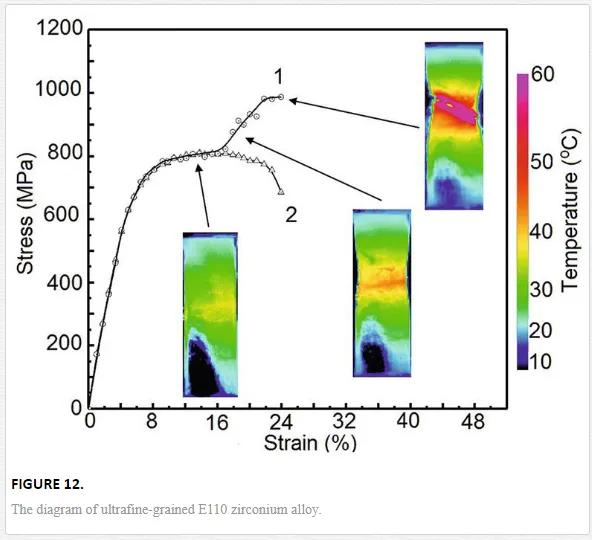
Curves of true stress-true strain are shown as Curve 1. Curves of engineering stress and strain are marked as Curve 2. The insets show the temperature distribution on the specimen surface under certain deformations.
Dimensions of specimens at thermograms for UFG titanium and zirconium alloys showed that the fractional decrease in the area at fracture of specimens is twice less ones in comparison with values of CG alloys. Deformation localization in the zone of necking caused a significant growth of true flow stress and increase of the hardening coefficient. Deformation localization is accompanied by local temperature rise.
The maximum temperature on the surface of CG titanium specimen raised proportionally to the strain rate up to a certain level (in the range from 50 to 55°C) and then increased sharply on ~5−10°C (up to the temperature 58.45−60.54°C) due to the localization of the plastic deformation near damages or crack.
The analyses of IR thermograms showed that character of temperature changing under deformation of UFG and CG titanium specimens is different. These results indicate that macroscopic regularities of strain localization in the UFG and CG titanium and zirconium alloys differ.
The maximum temperature of the UFG sample is directly proportional to strain rate and reaches a temperature of 50–58 °C, after that the temperature did not change much [28].
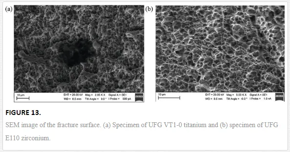
Figure 13 shows the SEM images of fracture surfaces of UFG titanium alloy and UFG zirconium alloy. Chains of micropores and microcracks are present on the fracture surface.
The maximum temperature at the surface of UFG zirconium alloy specimen increased from 40 to 68°C; then, there was an abrupt temperature decrease. This effect is caused by rapid damage accumulation and formation of macrocrack.
The grain size distributions of UFG zirconium and titanium specimens differ due to imperfect process of the intensive plastic deformation [29].
The results of the SEM study of fracture surface confirmed the difference of damage in the samples of UFG titanium and zirconium alloys.
The results of fractographic studies of the fracture surfaces and the results of quasi-static and dynamic tests prove that the fracture of UFG FCC and HCP alloys has the ductile character.
The experimental and theoretical results can be used to develop in defining equations for the UFG alloys over the last decade.
The constitutive equation for ultrafine-grained alloys covering a wide range of strain rates
The computational model is required to predict the mechanical behavior of ultrafine-grained FCC, HCP, and BCC alloys under dynamic loading. Therefore, constitutive equations taking into account the grain size of metal alloys were offered by Meyers et al. [4, 18], Armstrong and Zerilli [30], and Khan et al. [31, 32]. Mishra et al. modified the model of Johnson-Cook [33]. A satisfactory quantitative description of the mechanical behavior of FCC and HCP alloys with coarse-grained and ultrafine-grained structure can be achieved by changing parameters of the materials. This limits opportunities to use models for the prediction of mechanical behavior of ultrafine-grained titanium alloys under dynamic loadings.
Obtaining realistic predictions of yield and strength in a wide range of strain rates remains an important problem.
We have developed model of mechanical behavior of the alloys for studying of laws of deformation and fracture of UFG alloys in a wide range of strain rates [12, 34–36].
The approach of damaged medium with stress relaxation for numerical simulation of solid response under shock wave loading was used. The stress of material particle is considered as a result of two competitive processes. Increasing of stresses and internal energy is caused by external impacts. Relaxation of the shear stress and energy dissipation are caused by the increments of inelastic deformation.
The model uses the effective parameters of mechanical state and averaged parameters of mechanical properties (mass density, elastic constants, Grüneisen parameter, etc.).
We consider the possibility of damage accumulation during inelastic deformation of NS and UFG metals in consequence of limited ductility.
The local damage parameter D was used in the scalar form

where Δεp=∫t0tε˙eqpdtΔεp=∫t0tε˙eqpdt, ε˙peqε˙eqp is the equivalent of inelastic strain rate tensor, and εf is the average value of an inelastic strain of a material particle at fracture.
The local failure criterion of a material particle was used in the form

he constitutive equation of UFG alloy was determined for material particle in the form

here σij is components of the stress tensor, p is the pressure, Sij is components of the deviatoric part of the stress tensor, δij is the Kronecker delta, φ (D) is the function of damage, and the parameters with index m correspond to the condensed phase of the damaged material.
The equation of state, Mie-Grüneisen, was used to calculate the pressure [16]. The relaxation equation was used to calculate the deviator of the stress tensor in the undamaged phase material:

where d/dt is the Jaumann derivative, μ(m) is the shear modulus of the undamaged phase material, e˙(m)ije˙ijmis components of the strain rate tensor, and e˙p(m)ije˙ijpm is components of the inelastic strain rate tensor.
The deviator of the inelastic strain rate tensor was calculated in the framework of the theory of Hencky-Ilyushin:

The scalar function e˙p(m)eqe˙eqpm is defined by the sum of the components basing on physical modes of inelastic deformation by relations:

where f(dg) = 1 − exp(−[(dg − dg min)/δ]− n) and δ, dg min, and n are parameters of grain size distribution function, e˙peqe˙eqp is the equivalent rate of plastic strain rate, [e˙peq]disle˙eqpdisl is the equivalent rate of plastic strain rate due to dislocation movement, [e˙peq]dislnucle˙eqpdislnucl is the equivalent rate plastic strain rate due to heterogeneous dislocation nucleation, and [e˙peq]twe˙eqptw is the equivalent rate of plastic strain rate due to twinning.
We used experimental function f(dg) of grain size distribution in UFG metal alloys treated by the equal channel angular pressing (ECAP). The grain size distribution and the average grain size are varied after several passes of ECAP [4]. Therefore, the total increments of inelastic deformation will depend on specific volume of small grains.
Peculiarity of deformation laws of FCC and HCP groups of metals has to be described by various kinetics (Eq. (17)). Equations can be used in phenomenological relation forms [12, 14]:

where R is the gas constant; k is the Boltzmann constant; T is temperature; b is the modulus of Burgers vector; g ≈ 0.5 is the orientation coefficient; G0 and G2 are specific activation energy of dislocation movement and nucleation, respectively; v is the average dislocation velocity; G3 is the specific activation energy of twinning; dg is the grain size; ρm is a density of dislocation movement; ρ˙ρ˙ is the rate of dislocation nucleation; and Atw, n1, m1,q are the material constants.
Constants n, q, ΔG0, and ΔG2 are varied for FCC and HCP metals [14].
The precipitate hardening of metals can be described by Orowan’s equation [37]

where μ is the shear modulus, b is the modulus of Burgers vector, M is the material constant, r is the radius of particles, f is the concentration of particles, and ν is Poisson’s ratio.
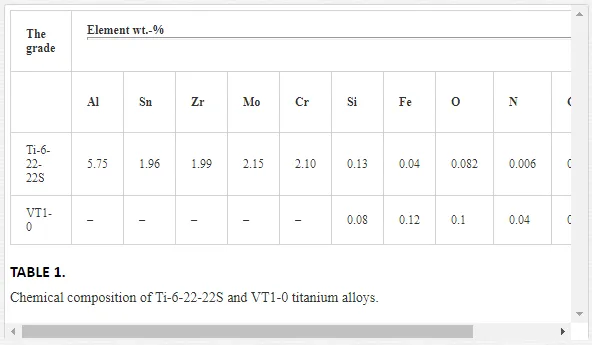
In Refs. [12–14], numerical values of model parameters have been discussed for UFG titanium alloys. Used numerical method has been discussed in [12]. Chemical composition of alloys is shown in Table 1.
Eqs. (10)–(17) were used for numerical simulation of high velocity impacts of plates. Calculated profiles of shock pulses in UFG titanium alloy are shown in Figure 14.
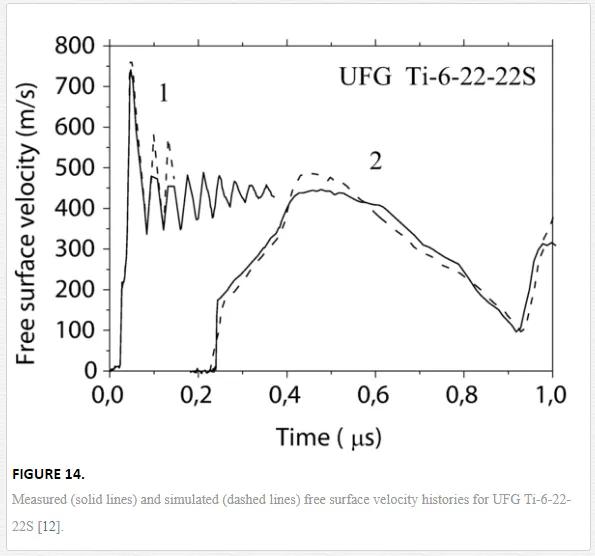
In simulated loading condition, UFG Ti-6-22-22S of 0.835 and 6.36 mm thicknesses was impacted by aluminum plates with 0.12 and 0.835 mm thicknesses at impact velocities of about 1250 and 680 m/s [15]. Dashed and solid curves indicate calculated and experimental profiles, respectively.
Results of computer simulation of shock loading of UFG alloys testify that fast relaxation of elastic precursor amplitude takes place at the first millimeter. Fast attenuation of elastic precursor can be explained by high rate of dislocation nucleation at grain sizes of several hundreds of nanometers.
Unlike coarse-grained alloys, strain hardening of fine-grained alloys at deformation under shock loading of several GPa is not enough. Satisfactory description of spall fracture was achieved in calculation too, in spite of a quasi-elastic unloading. We have not found considerable Bauschinger effect.
Figure 15 showed calculated stress-strain curves for Ti-6-22-22S. Solid curves correspond to experimental data. Dashed curves correspond to results of calculation.
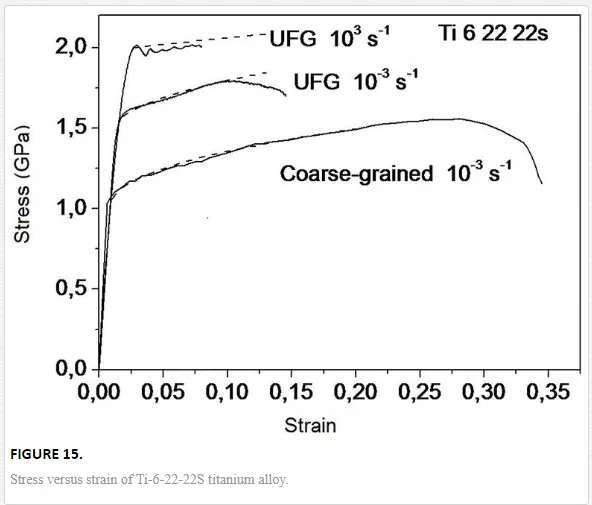
Stress-strain curves for UFG Ti-6-22-22S have a good agreement with experimental data at strain rates within the range from 10−3 to 103 s−1. Eqs. (15)–(16) allow us to describe the work hardening of titanium alloys in the range of deformation before necking.
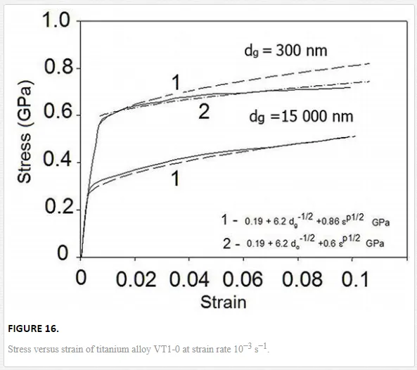
Figure 16 showed calculated stress-strain curves for VT1-0 titanium alloy.
Eqs. (15)–(16) describe the flow stress dependence on the strain rates and the plastic strains. Results of simulation of deformation of VT1-0 titanium alloy are shown in Figure 16.
Experimental stress-strain curves are shown as solid curves. The dashed lines 1 were obtained under assumption that k in the relation (Eq. (8)) is the constant for UFG and CG alloys. The dashed line 2 was obtained under assumption that k decreased when grain size became less 1 μm. These results are consistent with the experimental data for the UFG alloy, shown in Figure 3.
Figure 17 shows the logarithm of the shear stress versus the logarithm of normalized strain rate for coarse grain and UFG Ti-6-22-22S alloys. Experimental data are shown by symbols [12, 13, 38]. Curves 1 and 2 correspond to UFG and CG alloy, respectively. For normalization of the equivalent, strain rate was used ε˙peqε˙eqp=1 s−1. Analysis of the stress-strain rate data shows that the parameter m=d(lgσeq)/d(lgε˙peq)∣∣T,εpeqm=dlgσeq/dlgε˙eqpT,εeqpof strain rate sensitivity is less than that of CG Ti-6-22-22S alloy.
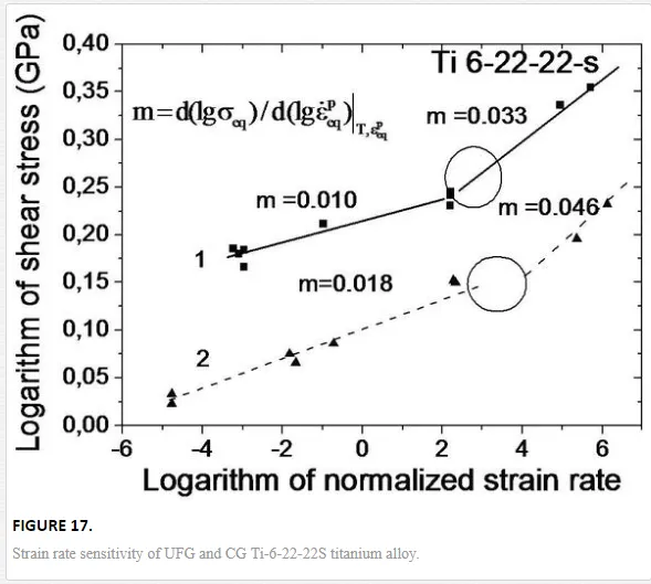
Change of curve slope at strain rates above ~103 s−1 testifies the change of dominant physical mechanisms of shear stress relaxation in both CG and UFG alloys. Thus, the constitutive equations for ultrafine-grained FCC and HCP metal alloys should have various forms likewise for coarse-grained counterparts.
The strain rate sensitivity index of the flow stress is determined by the relation

where σs is the flow stress; ε˙eq=[(2/3)ε˙ijε˙ij]1/2ε˙eq=2/3ε˙ijε˙ij1/2is the equivalent strain rate; and ε˙0=1.0s−1ε˙0=1.0s−1, m0, and Cm are the material parameters.
The strain rate sensitivity index of the yield strength is a private parameter value m at a predetermined value of εpeq=0.002εeqp=0.002.
Figure 18 shows the dependence of the strain rate sensitivity index m of the yield strength versus the inverse square root of the grain size. Experimental data are shown by symbols [39, 40]
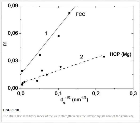
Curve 1 corresponds to HCP alloys; Curve 2 corresponds to FCC alloys. Filled triangles are experimental data [39]; filled squares are experimental data [40].
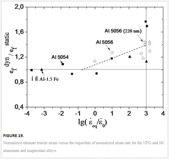
The tensile deformation to fracture under static loading increases with the decrease of grain size, as shown in Figure 19 [40]:

where εf static is the limit of plastic deformation to fracture under tension, dg is the average grain size, εf0, Dεf are structure-sensitive parameters of the material,θ = (T − Tr)/(Tm − Tr) T is the temperature in absolute scale, Tr =295 К is the room temperature, and Tm is the melting temperature.
The decrease of the strain to fracture under tension of UFG alloys is proportional to the logarithm of the strain rate in the range from 10−3 to 103 s−1 [5, 41]. Experimental data on the normalized ultimate tensile strain versus the logarithm of normalized strain rate for the UFG and NC aluminum and magnesium alloys are shown in Figure 19.
The dashed curve shows data obtained according to the formula

where εf is the strain to fracture, ε˙eq=[(2/3)ε˙ijε˙ij]1/2ε˙eq=2/3ε˙ijε˙ij1/2is the equivalent strain rate, ε˙0=1.0s−1ε˙0=1.0s−1, and Cεf is material parameter.
In the aluminum, magnesium, and titanium alloys, the formation of mesoscopic cracks is preceded by the stage of nucleation and growth of micro-voids. In this regard, the width of the plastic zone in the considered alloys will be determined by the critical size of voids.
Valiev et al. reported the log-normal grain size distributions for fine-grained polycrystalline metals processed by equal channel angular extrusion (ECAE) [42]. The distribution effect of grain size on the flow stress, ultimate strength at compression and tension, and elongation to failure has been shown to CG and UFG alloys [43, 44].
Starting with the pioneering work of Tellkamp et al. [45], the formation of bimodal distribution of grain size is used to produce ultrafine-grained and nanostructured alloys with high strength and satisfactory ductility. A bimodal distribution of grain size in UFG aluminum and magnesium alloys is the cause of several anomalies of the mechanical behavior. Negative strain rate sensitivity of plastic flow stress and increase of the ductility in a wide range of strain rates (from 10−4 to 1 s−1) were revealed for UFG Al–7.5 wt.% Mg, Al 5083, and magnesium alloys Mg-7wt.%Y [46–52].
The threshold value for the strain to fracture can be calculated by the rati

where εCGf0εf0CG is the strain to fracture of CG alloy; x is equal to dg− 1/2; A1, A2, x0, and x¯x¯ are material constants; T* = σsp/PHEL, P* = p/PHEL, and PHEL are the pressure in elastic precursor; and D1 and D2are material constants.
Increased crack growth resistance in Al-Mg alloys with a bimodal grain size distribution is a result of deflection of microcracks on borders between UFG and coarse-grained (CG) zones [53]. As a result of it, resistance to crack growth at mesoscale level increases with the increase of the plastic deformation.
Features of mechanical behavior of UFG alloys with bimodal grain size distribution are defined by shear band formation, nucleation and growth of damages, coalescence damages under formation of mesoscale, and macroscale cracks.
Thus, processes of shear banding in UFG alloys with bimodal and unimodal grain size distributions depend on strain rates.
Multiscale model of mechanical behavior of UFG alloys under dynamic loadings
The mechanisms of dynamic fracture in alloys with bimodal grain size distributions are poorly investigated. We present computational model and results of numerical simulation of damaging and fracture of aluminum and magnesium alloys under dynamic loading.
The multilevel computer simulation method was used for numerical research on damage and formation of cracks within structured representative volume element (RVE) of the alloy [34–36, 54]. Several types of grain structure that take place in alloys after severe plastic deformation were simulated.
Grain size distributions of aluminum and magnesium alloys after various numbers of passes of equal channel angular pressing (ECAP) are reported in Refs. [41–49]. The analysis of grain size distributions has shown that there are several types of grain structures. The model-structured RVE of alloys was created using the experimental data on grain structures.
Models of RVE have the volume fracture of coarse grains: 0, 5, 10, 15, 30, 50, 75, and 100%. When volume fracture of coarse grains exceeds the percolation limit (~0.25), the cell grain structures were taken into consideration. Mechanical behavior of alloy is described by means of averaging the mechanical response of structured RVE at the mesoscale level under loading of high strain rates. 3D models of representative volume element (RVE) of alloys with a bimodal grain size distribution have a dimension of 100 × 100 × 5 (μm)3.
Dynamics of RVE is described within approach of a continuum mechanics [14]. Smooth particle hydrodynamic (SPH) method was used for the simulation [54]. The kinematic boundary condition (Eq. (23)) is convenient when using SPH method. The boundary conditions (Eq. (23)) can be used for load combination of compression, shear, and tension. The scheme of boundary conditions is shown in Figure 20:

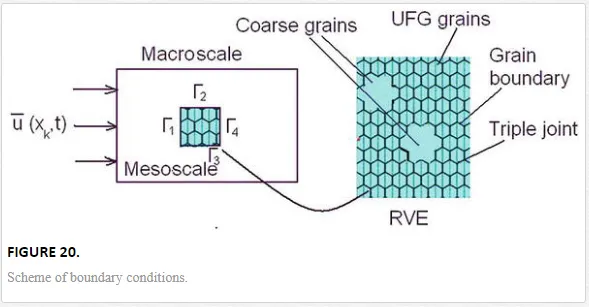
where xk is Cartesian coordinates, t is time, and uk is components of particle velocity vector.
The system of equations of continuum mechanics is applied to describe the deformation of the structured representative volume under loading conditions. Components of the strain rate tensor are described by the relation

where ε˙ijε˙ij is the strain rate tensor component, ui is the particle velocity vector component, and ∇i∇i is the Hamilton operator.
Components of strain rate tensor are expressed by the sum of the elastic and the inelastic parts:

where ε˙eijε˙ije is the elastic strain rate tensor component and ε˙nijε˙ijn is the inelastic strain rate tensor component.
The bulk inelastic strain rate is described by the relation

where D˙D˙ is the rate of change of the damage parameter.
The bulk inelastic strain rate will be equal to zero at D.=0D.=0 as follows from Eq. (26). In this case, to describe the plastic flow can be used in the theory of plasticity, which assumes the implementation of the postulate of constant volume for plastic deformation. However, the plastic deformation of NS or UFG alloys is accompanied by the damage (microcrack) nucleation and accumulation due to the limited ductility of the grains.
However, plastic deformation of NS or UFG alloys is accompanied by the nucleation and accumulation of microdamage (microcracks or pores) due to the limited ductility of man-sized grains.
The damage parameter D was introduced in the form

A local fracture criterion (Eq. (11)) was used for the UFG and the NS alloy with unimodal and bimodal distribution of grain size. The model uses Eq. (28) and phenomenological relation for the threshold inelastic strain εnfεfn.
D amage parameter is defined by the relation
and εnf0εf0n, k, C1, and C2 are the parameters for the local volumes of the material with unimodal distribution of grain size: epij=[(2/3)enijenij]1/2,εnij=(1/3)εnkkδij+enijeijp=2/3eijneijn1/2,εijn=1/3εkknδij+eijn, σeq = [3/2SijSij ]1/2, σij = − pδij + Sij, and δij is the Kronecker delta.
Eq. (12) was used as a constitutive equation of material particles. The pressure was calculated by polynomial equation of state [12]. The stress tensor where dg is the grain size of mesoscale region with the unimodal distribution of grain sizes; p is the pressure; deviator is calculated by Eq. (13). The deviator of the inelastic strain rate tensor is calculated by Eq. (14).
The scalar function e˙p(m)eqe˙eqpm is defined by the sum of components based on physical mechanisms of inelastic deformation by Eq. (16).
The total plastic work per volume unit under high strain rates was calculated by the relation

where σij is the stress tensor component, εnijεijn is the inelastic strain rate tensor component, and tf is the time of inelastic deformation before local fracture.
The local increment of temperature due to dissipation of plastic work at high strain rate was calculated by the equation

where ΔT is the temperature increment associated with plastic deformation, β is a phenomenological parameter, Cp is the specific heat of material, and ρ is the mass density:

where ε0 is the yield strain and n is the hardening exponent of the material.
Eqs. (10)–(15) and (24)–(31) were used for describing mechanical response of structured RVE of FCC and HCP alloys under dynamic loadings.
The distribution of grain sizes is specified in the model of a representative volume of the alloys.
Model RVE of alloys with a bimodal grain size distribution includes separate large grains and the volumes consisting of fine grains. RVEs taking into account the distribution of grain size similar to those identified in samples of UFG aluminum alloy Al 1560 (Al-Mg) and magnesium alloy MA2-1 (Mg-Al-Zn) were used for model calibration. Parameters of materials in constitutive equations were discussed in Refs. [12, 34, 53]. Numerical method was discussed in Refs. [12, 34–36].
The equivalent stresses in UFG magnesium alloy with quasi-regular grains structure at the time ~15.7 ns under shock wave loading with peak stress of 3.8 GPa are shown in Figure 21.
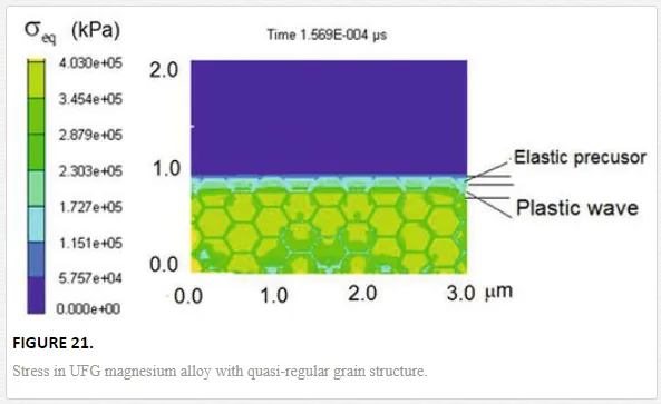
The width of shock wave front is less than the average grain size ~300 nm in the model of NS aluminum alloy with regular grain structure. Mechanical behavior of aluminum alloys with similar grain structure under quasi-static loading was discussed in Ref. [55].
A distribution of material particle velocities was found on the mesoscale level. The distribution of particle velocities arises from the wave interaction with grain boundaries and triple joints of grains.
The distribution of the parameter of damage behind the front of a shock wave with a peak stress of 3.2 GPa is shown in Figure 22. Two large grains with size of ∼20 μm are contained in the model volume of the alloy. These large grains were surrounded by UFG phase with average grain size ∼1 μm.
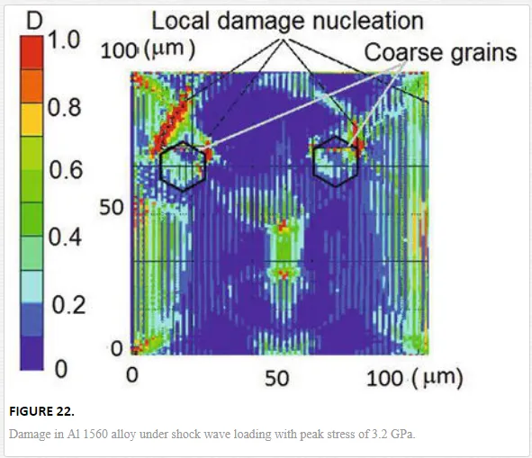
Deformation of RVE occurred nonuniformly under shock compression. Shear bands have been formed in the UFG phase at high strain rates. Damage to the mesoscale shear band was formed in 40 ns. The damage parameter increased rapidly when the local tensile stresses acted in areas filled with small grains and on the border between large grains and fine grains. Fracture of RVE is a result of the formation of flat clusters of damaged particles.
The distribution of grains size affects on the formation of damage and the distribution of the specific plastic work per unit volume over the RVE. The distribution of specific plastic work in RVE is shown in Figure 23. The size of large grains and its specific volume was ~20 μm and ~38%, respectively.
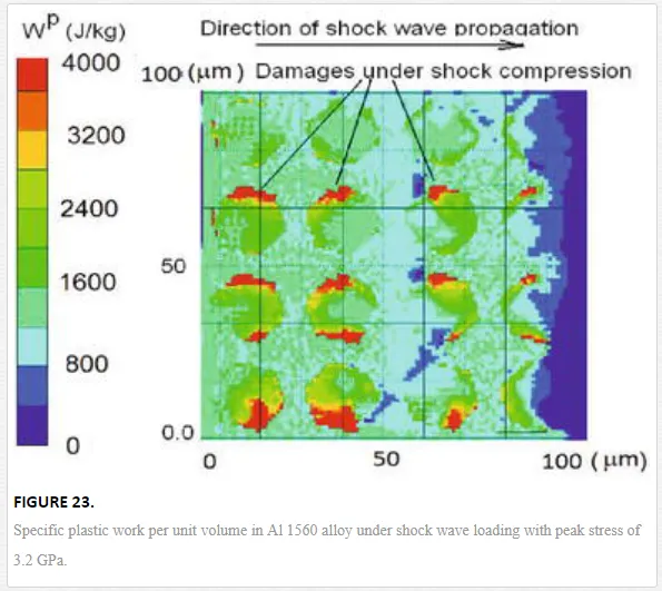
The damage parameter increased in local areas where the maximum values of plastic work have been achieved. Fracture mechanisms of alloys with bimodal distribution of grain size are similar in compression and tension. Damage also accumulates in the zones of plastic strain localization near borders of large grains of alloys with a bimodal distribution of grains. Specific plastic work per unit volume and equivalent plastic strain are shown in Figures 23 and 24, respectively.
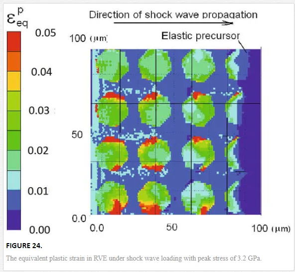
Therefore, kinetics of fracture depends on the specific volume of coarse grains.
The equivalent plastic strain in RVE of Al 1560 alloy under shock compression with peak stress of 3.2 GPa is shown in Figure 24. The average intensity of plastic deformation in coarse grains is higher than in the volume filled with fine grains. The maximum equivalent plastic strain is localized in a fine-grained phase near the boundaries of large grains.
Figure 25 shows the calculated plastic work under the tension of RVE at high strain rates. The tensile loading at high strain rates is realized in the spall zone where interaction of unloading waves takes place.
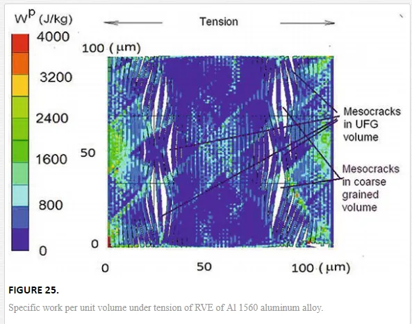
Mesoscale cracks in fine-grained volume formed under a tensile strain rates above ~103 s−1. The presence of large grains prevents the rapid growth of these cracks and leads to an increase in plastic work per unit volume. Thus, UFG alloys with bimodal distribution of grain sizes under dynamic loading have a higher ductility compared to UFG counterparts with unimodal distribution of grain sizes.
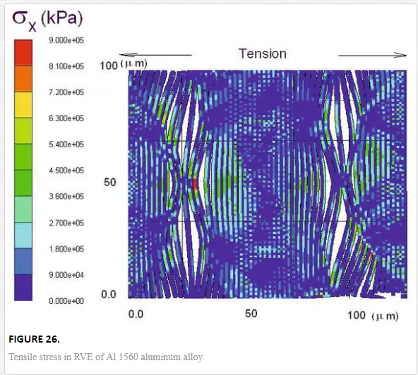
Tensile stress in the spall zone is shown in Figure 26. The representative volume of Al 1560 aluminum alloy consisted from ~75% of large grains with a size ~20 μm. The average size of fine grains was assumed equal to 1 μm. The relaxations of stresses in a spall zone have been accelerated by the damage accumulation.
The use of multi-pass ECAP leads to stochastic distribution of large grains in the volume of alloys. As a result, fracture of UFG alloys with bimodal grain size distribution under dynamic loading has probabilistic character. Large grains can be formed in the NS and UFG alloys as a result of dynamic recrystallization [56, 57].
In the used model, Eq. (18) takes into account the influence of nanostructured precipitates on dislocation kinetics. Wang et al. showed that in the UFG Al the deformation mechanism is operated by the dislocation interactions at high strain rates, while in the lower strain rate range, the deformation mechanism may be related to grain boundary sliding [58].
The increase in the concentration of nano-size precipitates leads to the growth of the yield stress of both large and small grains of alloys. The concentration of precipitates in UFG alloys affects the grain size distribution and the distance between the shear bands. These results agree with experimental data [59]. Chrominski et al. showed that the grain size, grain boundary character, and dislocation substructure are strongly depended on the precipitation in 6082 aluminum alloy. It was found that needlelike precipitates are homogeneously distributed in the grains of micron-size [59].
The ductility of UFG alloys increases when a specific volume of coarse grains is decreased. The ductility versus specific volume of coarse grains in Al-Mg alloy with a bimodal grain size distribution is shown in Figure 27. Experimental data [45, 48, 49] are shown by filled symbols. Decreasing of the specific volume of large grains in RVE of UFG alloy is accompanied by a decrease of average strain to failure under quasi-static and dynamic loadin
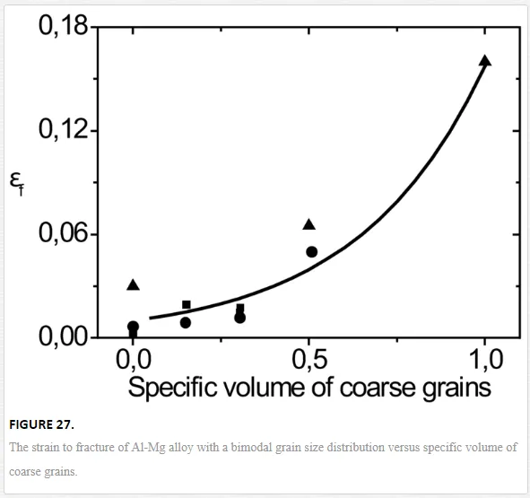
Figure 28 shows the dependence of strain to fracture of aluminum and magnesium alloys on logarithm of strain rates.
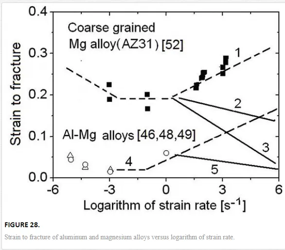
Experimental data reported by Ulacia for coarse-grained magnesium alloy AZ31 are marked by filled symbols [60]. Data for aluminum alloys are shown in circular and triangular symbols [48, 49]. UFG Al-Mg alloys have fine-grained size of 1 μm and coarse-grained size of 20 μm.
The calculated values of total strain to failure of coarse-grained magnesium alloy AZ31 versus the logarithm of strain rate are depicted by dashed Curve 1 in Figure 28. Rodriguez [61] later received that the experimental values of strain to failure of AZ31 alloy at quasi-static loading conditions confirmed the adequacy of the prediction.
Curve 2 shows the calculated strain to fracture of Ma2-1 magnesium alloy with volume concentration of large grains about ~70%. Curve 3 shows strain to fracture for magnesium alloy with specific volume of large grains about ~10%.
Curve 4 shows the ductility of Al-Mg alloys with a bimodal grain structure in a wide range of strain rates. Curve 5 displays decreasing dynamic ductility of Al-Mg alloys with a bimodal grain structure and specific volume of large grains ~10%.
The plasticity of the alloys under quasi-static tension increases when specific volume of large grains in UFG Al-Mg alloy is more than 30%.
The calculated strain to failure for Al-M alloys can be described by the equation

where εnfεfn is the strain to failure under quasi-static tension and Ccg is the specific volume of coarse-grained size.
Eq. (32) describes ductility of UFG Al-Mg alloys with a bimodal grain distribution versus the specific volume of large grains. Results of simulation agree with the available experimental data [48, 49, 52].
Conclusions
The study of the mechanical behavior of NS and UFG alloys under intensive dynamic loadings allows you to deepen understanding of the basic laws of deformation and failure of alloys in extreme states.
Experimental studies have shown that the difference between the Hugoniot elastic limits of alloys with UFG and CG structure can be negligible.
The spall strength and the yield strength of UFG alloys are depended not only on grain size but also on distribution of grain sizes, a concentration of a nano-sized precipitates.
Fine precipitates in alloys not only affect the hardening but also lead to change the influence of the grain size distribution on volume concentration of shear bands.
Multiscale computer modeling can be used to study the regularities of deformation and fracture of advanced structural alloys at high strain rates.
It was shown that the use of models taking into account the unimodal and bimodal distribution of grain size allows predicting the strength and ductility of a UFG alloys at high strain rates under compression and tension.
The results of computer simulation showed that the dynamic strength and ductility depend on the distribution of grain size in the HCP and FCC alloys processed by severe plastic deformation.
Experimental and numerical studies have shown that strain to failure of UFG alloys with a bimodal grain size distribution nonlinearly decreases with the increase of specific volume of submicrometer grains.
The dynamic ductility of UFG alloys is decreased when specific volume of submicrometer grains is above ~70%.
It should be noted that researches on the influence of grain size distribution of UFG alloys on dynamic strength and ductility are at an early stage. The peculiarities of the mechanical behavior of UFG alloys under dynamic loading at elevated temperatures are insufficiently studied


