Introduction
Carbon nanotubes (CNTs) are hollow cylinders consisting of single or multiple sheets of graphite (graphene) wrapped into a cylinder. After the first observation in 1991 by Iijima [1], extensive work has been carried out to CNTs toward their broad mechanical, electronic, thermal, and optical applications [2, 3]. The fundamental mechanical properties, such as their stiffness, strength, and deformability, have been investigated with extensive theoretical and experimental researches, and been well reviewed, in the past two decades [4–8]. Nowadays, for industrial and engineering applications, CNTs have been assembled into macroscopic materials such as fibers, films, forests, and gels [9–15]. Due to the assembly feature of these materials, the interfacial structure between CNTs always plays a crucial role in determining the tensile or compressive behavior, dynamic response, and coupling phenomenon between multiple physical properties that take place at the interfaces. Therefore, the utilization efficiency of the mechanical property from individual CNTs to their assembly is a sophisticated function of the assembly structure and types of interfacial interactions.
In this chapter, I will review the mechanics of individual CNTs, discuss the sliding friction between CNTs, and report our recent progresses on the fabrication technique and mechanical properties of macroscopic CNT assembly materials. The general features of the assembly design and interface design will be illustrated from the perspective of interface engineering. The chapter is organized as follows. Section 2 contains a brief description of the mechanical properties of individual CNTs, in terms of modulus, strength, compressibility, and deformability. Section 3 describes the interlayer (intershell) sliding of multiwalled CNTs (MWCNTs) and intertube friction between adjacent CNTs, and the strategies to enhance the interfacial frictions. Section 4 discusses the recent investigations on the interfacial mechanics in macroscopic CNT assembly materials, especially CNT fibers and films where the CNTs are highly aligned or highly entangled. Finally, the chapter concludes with a brief summary and gives an outlook on future developments in the field.
Mechanical properties of carbon nanotubes
YOUNG’S MODULUS AND TENSILE STRENGTH
The basic mechanical properties of CNT are strongly related to the basic properties of a graphene sheet. In these materials, carbon atoms are covalently bonded with three nearest carbon atoms in a hexagonal lattice by forming three σ bonds in the sheet plane and one delocalized π-bond over the basal plane. As the sp2 σ bond is shorter and stronger even than the sp3 bond in diamond, the axial elastic modulus of CNT and graphene is super high, as expected to be up to several TPa [6, 7]. The first experimental study on the modulus was based on the analysis of thermal vibration of MWCNTs, which showed a wide range of 0.4–4.15 TPa [16]. Later, the modulus was also estimated by the compressive response using micro Raman spectroscopy and was 2.8–3.6 TPa for singlewalled CNTs (SWCNTs) and 1.7–2.4 GPa for MWCNTs [17]. Direct tensile tests showed the modulus ranged from 270 to 950 GPa for individual MWCNTs [18], and from 320 to 1470 GPa when several SWCNTs bundled together as a CNT rope [19]. Besides the experimental evaluations, theoretical estimations also show the similar results. For example, by using an empirical Keating Hamiltonian with parameters determined from first principles, a modulus ranging from 1.5 to 5.0 TPa was estimated [20]. A molecular dynamics (MD) approach showed a modulus of ~1 TPa and a shear modulus of ~0.5 TPa and predicted that chirality, radius, and number of walls have little effect on the value of Young’s modulus [21].
Different from the modulus estimation, measuring the tensile strength of CNTs is a very challenging task. Compared with experiment, it is easier to compute the strength by considering the effects of defects [22, 23], loading rate, temperature [24], and number of walls [25]. Typically, the fraction of CNT involves bond breakage and/or rotation, usually resulting in the formation of specific types of dislocation, such as the pentagon-heptagon (5-7), (5-7-7-5), (5-7-5-8-5) defects [26]. MD simulations showed that CNT under tension behaves as a brittle material at high strain (15%) and low temperature (1300 K), or as a ductile material at low strain (3%) and high temperature (3000 K) [26–28]. Such tensile behaviors depend on the evolution of the dislocation. For example, the (5-7-7-5) dislocation can either separate into two (5-7) pairs to result in a ductile transformation or involve into a crack to result in a brittle fracture. An alternative pathway for the fracture of CNT was also proposed by the direct bond-breaking through the formation of a series of virtual defects at high tensions [23]. These studies were usually based on the consideration of the formation of energy for the dislocations. However, another MD study showed that the fracture behavior is almost independent of the separation energy and to depend primarily on the inflection point in the interatomic potential [22]. The fracture strength should be moderately dependent on tube chirality, and the strength and fracture strain were estimated to be 93.5–112 GPa and 15.8–18.7%, respectively. Figure 1a shows two different stress-strain curves for a (20,0) CNT, where the modified Morse potentials with interatomic force peaks at 19 and 13% strain were used. To show the effect of structural defect, a result for a missing atom is provided where the strength was reduced by about 25%.

The tensile strength and the fracture of CNT were also measured directly with experiment [18, 19]. The measurement of 19 MWCNTs showed a strength of 11–63 GPa and a strain at break up to 12% [18]. The failure of MWCNTs was described in term of the “sword-in-sheath” type fracture, where the outermost shell broke first followed by the pull out of the rest of the shells from the outermost shell. When SWCNTs were bundled to be a rope, the tensile strength was measured to be 13–52 GPa, based on 15 measurements, and the strain at break was up to 5.3%, see Figure 1b [19]. The stretchability of CNT was also experimentally obtained by deforming freely suspended SWCNT ropes, where the maximum strain was up to 5.8 ± 0.9% [29]. By measuring the stress-induced fragmentation of MWCNTs in a polymer matrix, the tube strength was up to 55 GPa [30]. Another pulling and bending tests on individual CNTs in-situ in a transition electron microscope (TEM) showed a tensile strength of ~150 GPa, suggesting that the strength is a large fraction of the elastic modulus [31].
COMPRESSIBILITY AND DEFORMABILITY
Different from the high rigidity and high strength along the axial direction, CNT is relatively compressible and deformable in the transverse direction. When individual SWCNTs are bundled together, significant deformation could occur by van der Waals (vdW) interaction between the adjacent tubes [32]. Fully collapsed MWCNTs were first observed with TEM [33]. Large diameter CNTs could also form the partial and full collapse on substrate [34–36]. The structural deformation can be induced by applying pressure. Various experiments on SWCNT bundles have shown clear evidence of structural deformation or transition [37–42]. MD simulations revealed that the compressibility and deformability are dependent on the tube diameter and the number of walls [43]. By applying a certain high pressure, there could be a circular-to-elliptical shape transition of the tube’s cross section for either individual CNTs or their bundles [44–51]. These structural deformations are all reversible upon unloading the pressure. In a different way, a very large force exerted on CNT could still produce reversible and elastic deformation, and that radial mechanical forces might not be capable of cutting a CNT [43]. By examining the ballistic impact and bouncing-back processes, large diameter CNTs could withstand high bullet speeds [52].
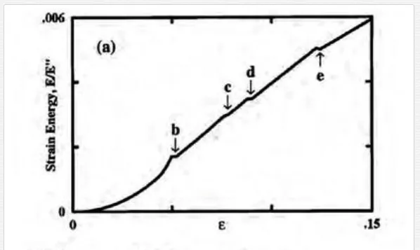
Upon compressing, bending, or twisting, structural deformations of CNT become more complicated. With an increasing compression stress, different buckling patterns in CNT at the point of instabilities can be created [53]. As shown in Figure 2, each shape change corresponds to an abrupt release of energy and a singularity in the stress-strain curve. MD simulations showed that the presence of intertube vdW interactions tends to weaken the CNT bundles under compression [55]. On the other hand, with increasing the tube diameter, the bending modulus was found to decrease sharply [56], as a rippling mode becomes energetically favorable [57, 58]. The modeling on the wavelike distortion indicated that there is a critical diameter at a given load and a CNT length, for the emergence of the rippling mode [59]. It was also found that thick MWCNTs are very prone to develop rippling deformations in bending and twisting, governed by the interplay of strain energy relaxation and intertube interactions [58, 60]. Figure 3 shows experimental observations of partially collapsed segments in freestanding and twisted MWCNTs with TEM [54].

Interlayer and intertube interactions
SLIDING BETWEEN MWCNT SHELLS
Different from SWCNTs, the interlayer interactions in MWCNTs exhibit interesting sliding phenomena during the tensile stretching and self-oscillation. By modeling of the interlayer interaction with different atomic potentials, such as the classic Lennard-Jones (LJ) potential and the registry-dependent Kolmogorov-Crespi (KC) potential (zeroth generation RDP0 [61] and first generation RPD1 [62]), could cause significantly different energy corrugation between graphitic layers [62–65]. Nevertheless, the interlayer sliding has been systematically studied despite the type of atomic potential. Experiments have also shown the interlayer sliding and superlubricity of CNTs.
Experimental measurements on the dependence of the sliding force against the contact length between the MWCNT shells suggested several responsible sources including the surface tension, the shear elastic force, and the edge (tube termination) effect force [66]. The shear strength was found to be 0.08–0.3 MPa depending on the interlayer commensurability. After the inner shells were pulled out from the outer shells, spontaneous retraction was observed with TEM due to the attractive vdW forces between these shells [67]. The interlayer static and dynamic shear strengths were estimated to be 0.43–0.66 MPa. The telescoping motion of an MWCNT also showed an ultralow friction, below 1.4 × 10⁻¹⁵ N per atom (8.7 × 10⁻⁴ meV Å−1) [68]. More direct observation of the superlubricity in doublewalled CNTs (DWCNTs) was conducted by extracting the inner shell out from a centimeters-long DWCNT, where the inner-shell friction (vdW force) was estimated to be 1.37–1.64 nN (the total number of atoms was unknown, yet could be over 108–109 for a tube length of 1 cm) [69], corresponding to a friction force of about 10−6–10−5 meV Å−1 per atom. By following the low-friction induced telescoping, gigahertz oscillators were theoretically proposed based on the oscillatory extrusion and retraction of the inner shells [70–77], and the interlayer commensurability determines the rate of energy dissipation during the oscillation [71]. The friction force between oscillatory layers was estimated to range from 10−17 to 10−14 N per atom, about 6 × 10⁻⁶–0.006 meV Å−1 [73]. Similarly, the rotation between CNT shells and the rotational friction was observed or measured by experiments and simulations [78–81]. The rotational friction is a broadband phenomenon, as it does not depend strongly on a specific vibrational mode but rather appears to occur from the aggregate interactions of many modes at different frequencies [82].
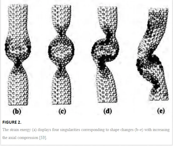
At high sliding speeds, the friction between CNT layers was not hydrodynamical, in fact not even monotonic with the sliding speed [83]. A high speed can develop a sharp friction peak and onset parametric excitation of CNT’s “breathing” phonon modes. Figure 4a shows that there is a massive increase in sliding friction at a speed of ~1100 m s−1 for a (5,5)@(10,10) DWCNT. The highest friction force could be up to 170 pN, corresponding to ~0.15 meV Å−1 per inner tube atom. The main source of the interlayer friction was believed to be the inner nanotube terminations [85], while the “bulk” friction was unfortunately considered to be irrelevant.

To understand the “bulk” frictional behavior, two groups of studies were carried out [65, 84, 86]; pulling simulations where a constant external force was applied on each atom of the inner tube along the tube axis, and rigid sliding simulations where the inner tube was constrained to slide as a whole at a fixed speed. The pulling simulation revealed a static friction (depinning) force of 0.02 meV Å−1 at 300 K and 0.1 meV Å−1 at 50 K for the (5,5)@(10,10) DWCNT. After the depinning, the speed of the inner tube jumps directly to plateaus. Three speed plateaus are seen at v ≈ 450, 720, and 780 m s−1. This phenomenon is ubiquitous as it is also observed for an incommensurate case where a chiral (11,2) tube slides inside a (12,12). The general occurrence of plateaus and jumps is a natural consequence of frictional peaks for growing the speed. Figure 4b shows sharp frictional peaks near v ≈ 450, 570, 720, and an important threshold onset near 780 m s−1. These peaks are known to generally arise out of parametric excitation of the “breathing” phonon modes, classified by an angular momentum index n(for tangential quantization around the tube axis). Such nonmonotonic force-speed characteristics imply a “negative differential friction,” whereby an increasing applied force yields an inner tube sliding speed that grows by jumps and plateaus, rather than smoothly.
The surprise comes from analyzing the two parts of angular momentum J = JCM + Jpseudo around the tube axis such as its center-of-mass (rigid body rotation with angular velocity ω) and shape-rotation (“pseudorotational”) parts [65, 84]. Generally, zero at generic sliding speed due to lack of nanotube chirality, Jpseudo = −JCM = 0, Jpseudo jumps to nonzero values at the frictional peaks and past the threshold, where Jpseudo = −JCM / ≠ 0, see Figure 4b. This is a spontaneous breaking of chiral symmetry occurring in nanoscale friction, whose mechanism is from the third- and fourth-order energy nonlinearities. The inner-tube sliding causes a washboard frequency due to the lattice periodicity aCC = 2.46 Å. At the critical frequencies, the ‘n = 5’ or ‘2 + 3 = 5’ excitations are observed, where the DWCNT’s n = 5 mode is resonantly excited or the n = 2, 3, 5 modes are jointly excited by the simple matching condition 2 + 3 = 5. Besides these “normal” excitations (labeled A in Figure 4b), there are ‘n= 5s’ and ‘2 + 3s = 5’ excitations, where the 3s and 5s are the single outer tube’s phonon modes. These excitations are labeled B in Figure 4b. The two C-peaks in Figure 4b are ascribed to the phenomenon of strong stick-slip frictions, possibly related to the phonon modes along the tube axis.
INTERTUBE FRICTION
In most of the cases, individual CNTs are bundled together as a CNT rope, owing to the strong aggregation tendency between adjacent CNTs. As mentioned above, experimental measurement showed a tensile strength just up to 13–52 GPa [19], far below the ideal strength for individual CNTs. The easy sliding between adjacent CNTs has become a severe problem hindering their engineering applications. For example, slip rather than breakage of individual CNTs was observed in the fracture test of polymers reinforced by CNT bundles [87]. As CNTs can contact with each other in parallel way or at certain cross angles, the interfacial shear strengths between CNTs should be discussed separately.
The static and kinetic frictions between two perpendicular CNTs were investigated experimentally. A coefficient of friction of 0.006 ± 0.003 was obtained by sliding an MWCNT perpendicularly on a SWCNT surface, and the shear strength was derived to be 4 ± 1 MPa [88]. The shear strength was one to two orders of magnitude larger than the intershell shear strength of 0.05 MPa for MWCNTs in vacuum, possibly due to the presence of water at the intertube interface in ambient. A following experiment, namely a vertical friction loop measurement, was proposed to characterize the adhesion and friction properties between CNTs [89]. An MWCNT tip was ramped in the vertical direction against a suspended SWCNT. During ramping, a stick-slip motion was found to dominate the sliding, attributed to the presence of defect-induced or amorphous-carbon-associated high energy points on the tip surface. Surprisingly, the coefficients of static friction and shear strength were finally evaluated to be about 0.2 and 1.4 GPa, respectively.
MD simulations showed that the sliding behaviors and interfacial shear strengths between two crossly contacting CNTs are much more complicated than the frictions between CNTs and graphite, graphite and graphite, and the inner and outer shells of MWCNTs [90]. The simulation was performed on two SWCNTs in contact at different cross angles. For the parallel contact, the axial interfacial shear strengths between the zigzag-zigzag (~0.25 GPa) and armchair-armchair pairs (~0.5 GPa) are two orders of magnitude larger than those of CNTs having different chiralities (0.5–1 MPa). CNTs with diameters larger than 1 nm will slide relatively from an AB stacking position to the next nearest AB stacking position while smaller ones do not slide through AB stacking positions. For two cross contacting CNTs, the magnitude of interfacial shear strength is much less dependent upon tube chirality. The highest value of shear strength was reported to be about 1 GPa in SWCNT bundles, however, still as quite low as to be improved for applications in high-performance composite materials [91].
STRATEGIES TO IMPROVE THE INTERTUBE LOAD TRANSFER
A molecular mechanics modeling showed that in order to make the strength of a CNT bundle as high as that of the lowest value of individual CNTs (11 GPa), the contact length should be up to ~3800 nm, by assuming the CNTs are bundled together without changing their circular cross sections [63]. With considering the vdW-force-induced radial deformation [32], the intertube distance-of-closest changes from 3.34 to 3.25 Å for (10,10) CNT bundles, the required contact distance for 11 GPa can decrease to ~1300 nm. This implies that the key to improve the intertube load transfer is the interface design between CNTs.
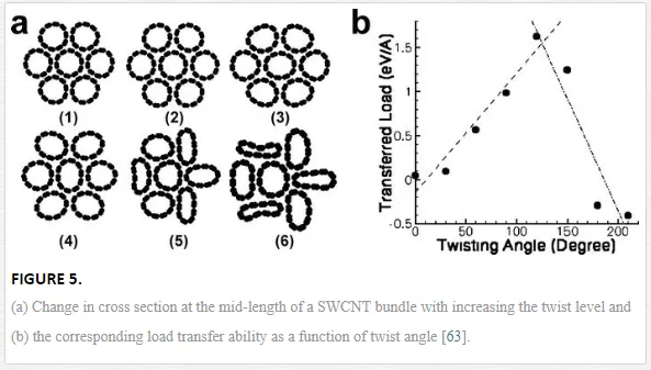
Twist is an effective way to induce strong radial deformation for CNT bundles. Figure 5a shows the cross sections obtained from MD simulations with increasing the twist level and Figure 5b shows the corresponding transferred load due to the shape deformation at twist angles of 0, 30, 60, 90, 120, 150, 180, and 210° [63]. It was observed that the individual CNTs start to collapse in the cross section, and therefore, more atoms are in close contact. For the case of no twist, a force of only ~0.048 eV Å−1 is transferred to the center tube, while at 120° the transferred load increases to 1.63 eV Å−1. Clearly, the radial deformation strongly depends on the twist angle, which consequently changes the nature of the contact and contributes to a new interlayer tribology.
Even a slight structural deformation could cause an improved load transfer. For example, when a DWCNT was slightly bent into a curved one, the energy transfer between the two tubes becomes much faster than that between two straight tubes [81]. Slight displacement of the inner tube could add a large degree of disturbance to the DWCNT’s original state of equilibrium and thus present strong inertia to oppose the extraction process, indicating the importance of the inner tube as structural support for the outer tube [92].
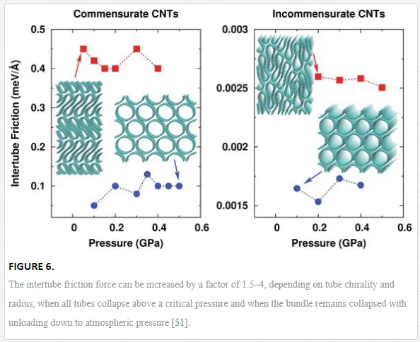
Pressure-induced structural phase transition could be a new strategy to improve the intertube load transfer [51]. For a CNT bundle containing 16 (23,0) SWCNTs, the intertube static friction can be improve from 0.1 eV Å−1 per atom to 0.4–0.45 eV Å−1 after all the tubes collapse under pressure higher than 0.5 GPa, see Figure 6. Due to the large tube diameter, the collapsed CNT structure can be well maintained even by unloading the pressure down to 0.05 GPa. In order to realize a 10 GPa tensile strength, the minimum tube length should be just 167 nm, much smaller than the length of 1090 nm before the phase transition. For a CNT bundle containing totally different tube chiralities, the dynamic friction force can be improved from 0.0017 to 0.0026 eV Å−1 after the phase transition. Such study also indicated that fewwalled large-diameter CNTs could be very important for engineering applications due to the easy ability to induce the collapse phase transition.
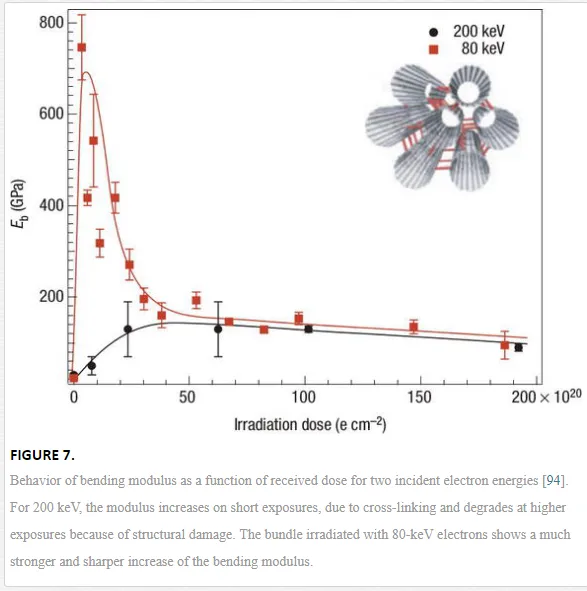
Covalent bonding between the shells in MWCNTs or between adjacent CNTs can increase the interlayer and intertube shear strength by several orders of magnitude [93–95]. The covalent intershell bonds can be formed due to the on-shell vacancies or intershell interstitials. According to the types of defect, the force needed to initiate sliding of the shells varies from 0.08 to 0.4 nN for a single vacancy to 3.8–7.8 nN for two vacancies, an intershell interstitial, and an intershell dimer [93]. Therefore, small-dose electron or ion irradiations are suggested to partially transfer the load to the nanotube inner shells. MD simulations revealed that interwall sp3 bonds and interstitial carbon atoms can increase load transfer between DWCNT walls and that interwall sp3 bonds are the most effective [95]. Similarly, by using moderate electron-beam irradiation inside a TEM, stable links between adjacent CNTs within bundles were covalently formed [94]. At a high irradiation energy of 200 keV, there was a substantial increase in effective bending modulus and thus an increase in shear modulus for low doses, while a long irradiation time rather damaged the well-ordered structure of tubes (Figure 7). At 80 keV, electrons were shown not to damage isolated CNTs but had enough energy to lead to the formation of mobile interstitial atoms in the confined space between adjacent CNTs. As a result of the newly formed covalent bonds, a huge increase of the bending modulus by a factor of thirty was observed (Figure 7). However, a long-time dose at low energies could still cause the accumulation of damage to the structure, making the mechanical performance to decrease eventually.
Even without introducing covalent bonding between the sp2 layers, the existence of structural defects in either CNT layer could lead to a sharp increase in friction and energy dissipation rate [64].
However, besides the tube structure, defect level, and intertube contact, there are many other issues in macroscopic CNT assembly materials. For example, the CNT packing density, alignment, entanglement, aggregation size, and surface functionalization could be important structural parameters, as to be discussed below.
Carbon nanotube assembly materials
So far, CNT fibers, films, forests, and gels are well-known and typical macroscopic assembly materials where the CNTs are the main constituents, especially at a mass fraction much more than 50% [10]. For example, CNT fiber is a one-dimensional assembly containing millions of individual tubes [9, 11–13, 15]. It has been found that CNT fibers could have much higher specific modulus and specific strength than those of commercial carbon and polymeric fibers. For the composite materials, there have been two different applications of CNTs such as a dispersion-based fabrication by using CNTs as reinforcing fillers in a polymer matrix [96, 97] and an assembly-based fabrication by directly assembling CNTs into composites [14]. In the former, the CNT content is strongly limited to be no larger than ~5 wt%, while in the latter, a small amount of polymer molecules (about 20–30 wt%) are used to strengthen the interfaces between CNTs. To describe these macroscopic CNT materials, different structural parameters are proposed and investigated in the past decade.
CNT FIBERS
CNT fiber can be produced by the coagulation-based “wet spinning” [98–101], the “direct spinning” from a CNT aerogel [102–104] or similarly from a pre-formed CNT film [105], and the “forest spinning” based on vertically aligned CNT forests [106–108]. A CNT fiber with a diameter of ~10 μm usually contains more than 106 individual CNTs. Such assembly feature is different from those well-known fibers for many years, which are usually a solid structure without internal interfaces. CNT fiber can also be considered a continuous length of interlocked “filaments” (CNT bundles), where the bundles are formed during the CNT growth rather than in the spinning process. As I have pointed out recently [109], although also being called as CNT yarn, CNT fiber is indeed not a yarn because the CNT bundles are not macroscopically processable. On the contrary, the basic components of a yarn, the long and parallel or interlocked filaments, are usually processable objects with a width larger than several micrometers [110].
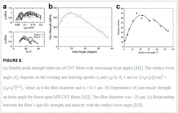
Twist is the most fundamental treatment to make the CNTs assembled into a continuous fiber with a circular cross section. The as-spun fiber is relatively loose with noticeable spaces between CNTs or CNT bundles when the twist angle is small. Increasing the twist angle is an effective method to densify CNT fibers and thus improves the friction coefficient between the CNTs. Figure 8 shows the strength-twist relationship for different CNT fibers [111–113]. All studies showed that the highest fiber strength was found at a twist angle of 15–20°. However, with further increasing the twist, the load (upon stretching) compresses the fiber rather than acts totally along the fiber axis due to the twist angle between the CNTs and the axis, making the utilization efficiency to decrease at high twist angles. The experimental observations that the strength initially increases with twist angle and then decreases are almost the same as those in traditional textile yarns. Nevertheless, the constituent CNTs are different from the filaments in a textile yarn; the CNTs are hollow cylinders and can deform the cross section under pressure due to a structural phase transition [44–49]. For those fibers spun from fewwalled CNTs (wall numbers smaller than 6), it can be seen that beyond the optimal twist angle, an additional strength peak is at large twist angle of 27–30°. This second peak arises from the collapse transformation of the CNT hollow structure, which renders the CNT bundles much stronger and reduces the bundle cross-sectional area.
Solvent densification is another interfacial treatment to CNT assemblies, due to a large capillary force [114, 115]. Therefore, liquid infiltration by using water, ethanol, acetone, or dimethyl sulfoxide (DMSO) is also often used in the method of array spinning to densify CNT fibers [116–119]. Although the densification process does not improve nanotube orientation, it enhances the load transfer between the nanotubes, thus ensuring that most of them are fully load-bearing. For example, the fiber diameter was shrunk from 11.5 to 9.7 μm after acetone shrinking [117]. However, the role of solvent is hardly known as the capillary force can be influenced by the solvents volatility (boiling point), surface tension, and interaction with CNT surfaces. By comparing various solvents including the nonpolar solvents of n-hexane, cyclohexane, cyclohexene, toluene, and styrene, polar protic solvents of glycerine, methanol, ethanol, water, ethylene glycol, and 1,3-propanediol, and polar aprotic solvents of ethyl acetate, acetone, acetonitrile, N,N-dimethylformamide (DMF), DMSO, and N-methyl-2-pyrrolidone (NMP), only few highly polar solvents show high densifying ability to CNTs, namely DMF, DMSO, NMP, and ethylene glycol, despite of their high boiling points and low evaporation rates [118]. These solvents increased the fiber strength from 864 MPa (dry-spun) or 1.19 GPa (ethanol) to 1.14–1.35 GPa (DMF, DMSO, NMP) or 1.33–1.58 GPa (ethylene glycol). Clearly, the solvent polarity shows a key role in determining the capillary, as the polarity induced attractive binding energy with CNT (Eind) goes up quadratically with the solvent’s local dipole moment μ, by Eind = −μ2α/(4πε0)2r6, where α is the static polarizability of CNT, ε0 is the vacuum permittivity, and r is the distance between the dipole moment and the CNT surface [120, 121].
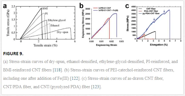
In addition to twisting and liquid densification, polymer impregnation is another effective treatment to enhance the mechanical properties of CNT fibers. The polymers are introduced to bridge nonneighboring CNTs, such as polyethyleneimine (PEI) [122], polydopamine (PDA) [123], polyvinyl alcohol (PVA) [105, 118, 124], polyacrylate [125], polyvinylidene fluoride (PVDF) [126], epoxy [105], polyimide (PI) [118, 127], and bismaleimide (BMI) [118, 128]. Figure 9 shows several typical stress-strain curves for polymer-reinforced CNT fibers, such as PI, BMI, PEI, and PDA [118, 122, 123]. The enhanced mechanical properties of CNT fibers with polymer impregnation are attributed to couplings between the CNT network and polymer chains occurring at the molecular level. As a result, the sliding between CNTs can be remarkably hindered by the polymer network, especially that formed by the cured thermosetting polymers. Therefore, more external strain can be transferred to the CNTs as shown in Figure 10, where the Raman peaks of CNTs downshift to a lower wavenumber by different values under axial strains [105]. Both PVA and epoxy enhanced the downshifts, corresponding to the improved load transfer between CNTs. The cured thermosetting polymer network also shows advantages in improving the fiber modulus, as indicated by the largest change in G’-peak wavelength. Similarly, PI and BMI are other efficient thermosetting polymers for producing high-modulus CNT fibers [118, 127, 128]. However, other polymers might be good at improving the fiber’s stretchability and toughness by preventing the sliding-induced fiber fracture, possibly due to the polymer wrapping around the CNT connections [126], cooperative deformation mechanisms of the soft and hard segments [125], iron-mediated covalent cross-linking [122], or cross-linked polymeric binders [123].

The structure of CNT fiber is hierarchical, with CNTs self-assembling into bundles and the bundles forming an aligned network in the fiber [129, 130]. Other assembly parameters also include the tube waviness or straightness [131], which can also result in different elasticity and modulus for CNT fibers. Notice that the above-mechanical improvements are irrelevant to the microstructure of individual CNTs but are relevant to the macroscopic assembly parameters. From the point of view of tube structure, fewwalled CNTs have shown advantages in producing high-performance fibers, rather than the ideal SWCNTs [131]. For the SWCNTs, usually 1–1.5 nm in diameter, simulations and experiments have shown that a certain high pressure (hundreds of MPa) is necessary to introduce even a slight deformation of their cross sections. That means, the intertube contact area is far limited compared with the overall circumference of the cross section. While for the fewwalled tubes, the tube diameter can be large up to ≥5 nm, making it much easy to deform the cross section and increase the contact area. Experiments even have shown, upon certain twisting and/or tensioning, collapse of fewwalled tubes were possibly introduced [111, 132].
Furthermore, covalent interface engineering could be an efficient posttreatment for the as-produced CNT fibers. Acid treatment could introduce rich hydroxyl, methyl/methylene, and carbonyl groups onto CNT surfaces, which also made CNT fibers shrunk slightly, or more densified. Such treatment enhanced the load transfer between CNTs, according to a theoretical study [94], and thus resulted in an increase in fiber strength and modulus [133]. Recently, by using an incandescent tension annealing process (ITAP), where the current-induced Joule heating increase the temperature of CNT fiber up to 2000°C in vacuum, sp3 covalent bonding was observed in CNT fibers [134]. As a result, the fiber modulus could be improved from 37 to 170 GPa, once the ITAP was performed with maintaining a high tension on the fiber.
In order to further improve the utilization efficiency of the individual CNT’s mechanical properties in CNT fibers, more effort should be paid to the delicate combining of the choice of CNT structure, controlling in CNT packing density, alignment, and straightness, and intertube mechanics engineering by polymers or covalent functionalization.
CNT FILMS
CNT films are another important macroscopic material with high mechanical performances. Various processing methods have been developed to produce CNT films by using preformed CNT assemblies, among which these two methods are of great importance: the layer-by-layer stacking of aligned CNT sheets and the stretching on entangled CNT webs [14]. Despite of the fabrication methods, there are also many common problems concerning with the interface mechanics, as the CNT fibers do.
For instance, liquid densification is widely used to CNT films [135–137], and polymer impregnation can remarkably improve the interfacial load transfer [138–143]. Different from CNT fibers where the tubes are assembled with the aid of twisting, there is more freedom to tune the assembly structure. The CNTs can be got superaligned by stretching the films in a wet environment [135], or by microcombing before they are layer-by-layer stacked [136]. After improving the CNT alignment, the pure CNT films could be as strong as 3.2 GPa in tensile strength, with a Young’s modulus of 124–172 GPa [135, 136]. Figure 11 shows the stress-strain curves for the CNT films being both densified and superaligned. Once these aligned CNTs were impregnated with polymers, especially thermosetting polymers, the film’s strength and modulus could be further improved. At a mass fraction of 50–55% for CNT, the CNT/BMI composite films exhibited a strength of 3.8 GPa and a modulus of 293 GPa [139]. Such superior properties are derived from the long length, high mass fraction, good alignment, and reduced waviness of the CNTs.

The stretching on entangled CNT webs is another way to obtain highly aligned CNT films. With the aid of BMI impregnation and curing, the strength and modulus of the CNT/BMI composite films could be improved from 620 MPa and 47 GPa (un-stretched) to 1600 MPa and 122 GPa, 1800 MPa and 150 GPa, and 2088 MPa and 169 GPa after being stretched by 30, 35, and 40%, respectively [140]. By further introducing surface functionalization for CNTs, the strength and modulus were surprisingly improved up to 3081 MPa and 350 GPa, respectively [141].
However, the direct stacking of CNT sheets and stretching on CNT webs could not avoid the CNT aggregation due to the vdW interactions. As shown in Figure 12a and b, the aggregation size was up to hundreds of nanometer [143]. Such aggregation of nanometer-sized components has become a severe problem in paving the way to stronger materials [144]. In the aggregation phase, the intertube load transfer is not as efficient as at the CNT-polymer interface. Thus, such aggregation phase becomes the weak parts in the composites and hinders further reinforcement. In an ideal structure, the nanometer-sized components should be uniformly distributed in the matrix without forming any aggregation phases. Therefore, all the interfaces can play roles in shear load transfer. As inspired by the formation process of natural composite structures, the BMI resins were infiltrated into CNT webs before any stretching was performed. Since the liquid treatment just densifies the CNT network without inducing CNT aggregation, the impregnation before stretching causes each CNT or CNT bundle uniformly covered by a thin layer of polymers. Therefore, the following stretching could just align the CNTs but avoid the aggregation due to the thin layer of polymer, resulting in an optimized composite structure. By adapting a multistep stretching process, the final composite film exhibited superior mechanical performances. The highest tensile strength and modulus were up to 5.77–6.94 and 212–351 GPa at a CNT-to-resin mass ratio of 7:3 and a stretching magnitude of 34% [143].
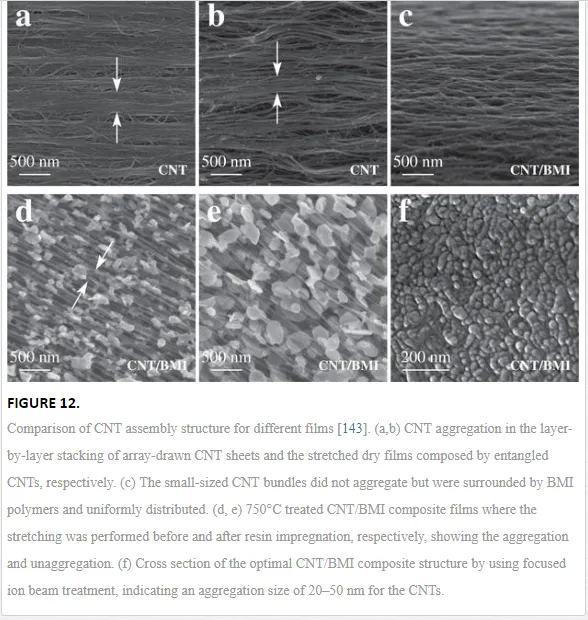
shows the morphology of the optimized CNT/BMI composites, where the CNT bundles were found to be uniformly distributed and aligned. To characterize the aggregation of CNTs, thermal treatment and focused ion beam treatment were used. After being heated to 750°C to decompose the polymers, the remaining CNTs were found to be aggregated/unaggregated if the stretching was performed before/after the polymer impregnation, see Figure 12d and e. The direct observation of the cross section with focused ion beam treatment showed an aggregation size of just 20–50 nm (Figure 12f), a size for the bundling that was still difficult to avoid during the growth process.
On the whole, for the macroscopic CNT assemblies, the interface mechanics becomes much more complicated as the material exhibits a collective dynamics from the constituent CNTs. Assembly parameters, including CNT packing density, alignment and/or entanglement, twisting level, cross-linking, and aggregation size, are found to be critical for the mechanical properties. By controlling the interface mechanics in the CNT assemblies, we can not only optimize the mechanical properties, but also introduce multifunctionalities, as discussed below.
MULTIFUNCTIONALIZATION BY INTERFACE ENGINEERING
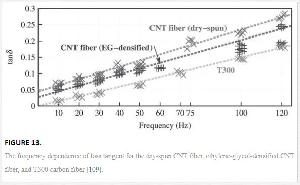
Besides load transfer at the intertube interfaces, energy dissipation is also a common interfacial phenomenon. As CNT fiber is formed by assembling millions of individual tubes, the assembly features provide the fiber with rich interface structures and various ways of energy dissipation, including the internal viscosity and intertube friction [109]. Therefore, a modified Kelvin-Voigt model was adopted, where an elastic spring K, a viscous damping coefficient η, and an intertube friction f are connected in parallel [145]. Due to the friction, there exists a friction-dependent component in loss tangent, which is not dependent on the frequency. As shown in Figure 13, the loss tangent was nonzero (about 0.045) for the dry-spun CNT fibers, while that for the T300 carbon fiber was nearly zero due to the absence of interfaces. When the CNT fibers were densified by ethylene glycol, the CNTs became constrained, corresponding to reduced loss tangents, see Figure 13. Based on the friction-based Kelvin-Voigt model, the damping performance of CNT fibers can be tuned in a very wide range. The introduction of thermosetting polymers further decreases the loss tangent, while plying CNT fibers into a yarn increases the loss tangent [109].
The CNT entanglement provides another way to enhance the damping ability [146]. The as-produced CNT films based on an injection chemical vapor deposition exhibited a loss tangent of 0.37–0.42 at 200 Hz [146], or 0.2 at 50 Hz [143]. After the network was stretched and strengthened with BMI, the loss tangent could decrease remarkably down to about 0.05 at 50 Hz [143].
When an electric current is passing through CNT assemblies, there exist parallel currents along the aligned CNTs. The collective electromagnetic force between parallel current can cause a volume contraction for the assembly [147]. Based on such mechanism, CNT fibers can be developed as electromechanical actuator. Detailed study revealed that the electromechanical coupling is quite complicated beyond the actuation [128]. For example, when a current passes through a CNT fiber, the fiber’s modulus could decrease remarkably due to the current-induced weakening in C−C σ bond. Besides the electromechanical coupling, the current could induce a strong Joule heating, making the fiber temperature to increase very sharply. Such electrothermal coupling can be used for fast curing to the impregnated thermosetting resins at a moderate temperature of 200–300°C [128], or for the formation of intertube sp3 covalent bonding at a high temperature of 2000°C in vacuum [134].
Conclusion
The control of interface mechanics is a key strategy to develop high-performance CNT assembly structures. High tensile properties (strength up to 3–6 GPa and modulus up to 200–350 GPa) can be obtained for aligned CNT fibers and films, corresponding to an improved utilization efficiency of CNT’s mechanical properties. Furthermore, the dynamical performance and multifunctionalities both depend strongly on the interface between CNTs, also in terms of CNT packing density, alignment, entanglement, twisting level, cross-linking, and aggregation size. For future development of high-performance CNT assembly materials, more delicate design on the multiscale interfaces is required. I hope this review could cast lights for the interface design ranging widely from the nanometer scale to the macroscopic scale.