
General information
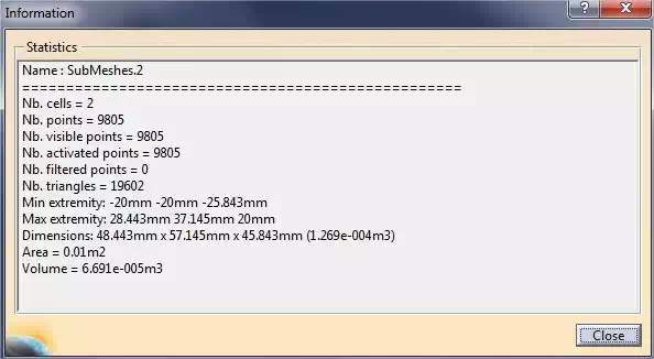
An “Information” icon that informs you about the geometry of the mesh can be found at the bottom of the toolbar.
Automatic error detection
Once your mesh has been generated, you can use the “mesh cleaning” tool in the side toolbar. This tool is quite limited as it merely permits errors detection. We will see in the next chapter how to fix them. The following window will appear. Click on “analysis” to see if your model contains errors or not.
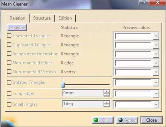
The mesh cleaning tool allows you to detect basic errors such as duplicated triangles, bad direction, edges and non-manifold vertices. A drop-down menu in front of each of the above errors allows you to assign a color to better identify the problem.
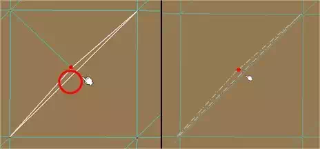
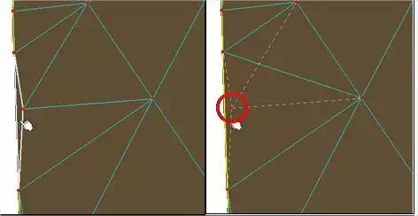
You can also apply filtering options of long edges and small angles, entering the values you want. Then clicking “apply”, affected points or edges related to the problems identified will be removed, as shown in the images below.
Choose a file format and export your model
CATIA works on a system of NURBS, which therefore allows you to easily save your model in STEP or IGES format. To do this, simply select one of these formats in the menu at the time of saving.
It is also possible, at the time of export, to convert your model to a file defined by a mesh, such as STL. It is indeed the most widely used format for 3D printing. Although CATIA does not directly support mesh modeling, you can generate one while exporting, which makes CATIA especially effective for 3D printing. CATIA allows import and export in this format, with quite a range of settings.
To export your model, you go through the STL rapid prototyping workbench (Start tab > Machining) or the Digitized Shape Editor module (Start > Form tab). The first workbench will be useful if you want to prepare your CAD model for 3D printing, while the second is more oriented towards processing point clouds from a 3D scanner. Both are quite similar except for a few tools.
Export is achieved by using the “STL export” button in the side toolbar.

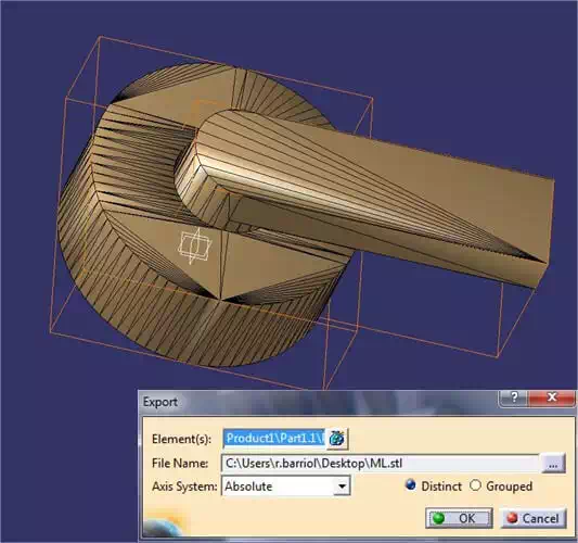
If your design is an assembly, several options are available to you when exporting. If you generated one mesh per part, then you can get a .STL file for each part. To do so, click on the icon “STL export.” Then click successively on the different meshes forming your assembly, and choose the “distinct” option. If, however, you want to get a single .STL file for your full assembly, then choose “grouped”. But be careful, “grouped” doesn’t mean “merged”. It just means that you will have only one file for the whole assembly.
Some files, by their complexity or nature, will not be optimal candidates for export to .stl. They will generate either very large files (over 500MB), or simply not be exported from CATIA below a certain level of accuracy.
Files with many curved / rounded parts or large areas based on vector drawings with a large number of points (text, graphics, etc.), will generally generate very large files in .STL.