Measuring elements and distances
While it is always easier to model directly using the right dimensions, thicknesses, and distances, it is sometimes necessary to measure parts of an existing volume. CATIA has two tools: Absolute measurement and relative measurement.
“Measure” tool
The relative measurement tool calculates the distances between any type of geometry: points, lines, planes, surfaces … The minimum distance is displayed. This tool measures either the distances between different bodies or simply a distance between different geometrical elements of a single body.
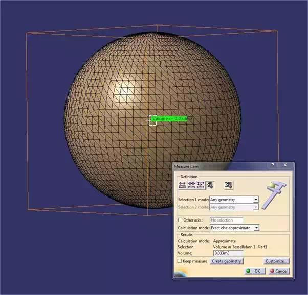
“Absolute measure” tool
The absolute measurement tool provides all the necessary information on a volume or a surface. It also helps with the “thickness measurement” to measure to a thousandth of a millimeter and very intuitively and quickly any thickness or length. In the case of a preparation of your CAD for 3D printing, an absolute measurement tool will be used to obtain volume information.
For dimensions, it is important to note that the concept of units is not valid for CATIA here. When exporting the file in a format other than native CATIA (.CATPart), the units are not retained. You’ll need to define the unit and scale appropriately when you move to the Sculpteo interface.
Mesh generation
“Tesselation” tool
This is the “tesselation” tool that allows you to generate the mesh. It is located in the sidebar.
You can now work on two main features, which will determine the accuracy of your model: sag and step.
The sag is the maximum distance between the mesh and the real shape.
Step corresponds to the distance between two neighboring nodes. Since both are dependent on each other, the default setting for step is ‘disabled’. You choose on what basis you want to control the accuracy of your model’s mesh.
We recommend that you keep the default setting and use the sag. Finally, note that the lower the values you choose, the more accurate your mesh will be, and of course heavier to export. Also note that the accuracy of the machines, being one micron, makes it unnecessary to enter a sag of less than 0.01mm.
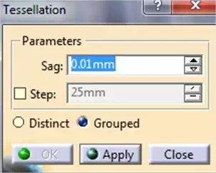
Finally, you can choose the grouped or separate option. If you have several pieces, the “grouped” option generates a single mesh for all parts. Conversely, choosing “distinct”, CATIA generates an independent mesh for each body part. Note that the mesh appears in the product/part which is activated in the tree.
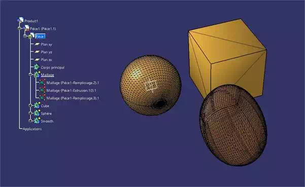
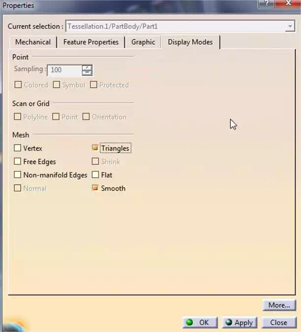
To view the mesh, which is not the default view, you need to access the mesh properties that appear in the tree (right click > properties display mode, check “triangles”).
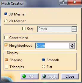
“Mesh regeneration” tool
This tool allows you to automatically re-mesh the model. This can be useful if you have a complex shape to mesh.