Bolted connections are common to many industries where standards (ASME, AISC, Sandia National Labs, ASTM, etc.) exist for bolt design procedures.
These regulations and recommended practices provide tools to size bolts and determine bolt torque loads based on the design environment. Yet, when it comes to including your bolted joint in your finite element model there is often confusion on how to proceed. How much detail is needed and how do I account for the bolt pre-load? Can I determine if I will lose my pre-load? Do I need to model the bolt? the nut? the threads?
Bolted connection analysis is no different than any other finite element calculation, in that the engineer needs to understand the analysis end goal prior to any calculations. Three basic requirements of a bolted connection are that the bolt must have adequate strength, the joint must remain intact and the connection must have adequate fatigue and fracture life. These requirements may or may not need to be addressed using the finite element method. The following list provides three levels of modeling recommendations based on the listed “assumed” analysis goals. They are listed in order of increasing level of finite element analysis complexity and accuracy, with each method requiring more work than the previous simulation:
1) “I just need the bolt loads and I will design my bolts by hand using industry standards, spreadsheets, etc. Cyclic loading is not an issue.”
(a) One does not need to always include the bolt in the finite element model, but can use shared nodes or couples to join two bodies. Forces and moments can then be extracted from the finite element model at these nodes and applied to the bolt design “hand” calculation.
(b) If there is a gap between the parts, use a rigid beam or multi-point constraint element to tie the two bodies together. Spoke elements or constraint equations can also be used to distribute the load locally so that singular stresses do not occur at the fastener (bolt head and/or nut) connection. Many finite element codes have automated features such as spot welds (Figure 1) that can be used to simulate this type of connection automatically.
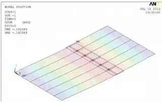
Figure 1: Spot Weld Modeling of a Series of Bolts using Beam Elements – Plate Deformation
2) “I need to understand the load history in the bolts to assure that the minimum and/or maximum bolt forces are not exceeded.”
(a) The components to be bolted together must have contact elements defined along their mating surfaces. The bolt needs to be modeled explicitly, but can be simplified using one or two beam element(s) to model the nominal bolt shaft. Bolt pre-load forces are typically generated in the first step of the analysis using one of the following methods:
i. Constraint equations (The bolt is split into two elements and a relative overlap is induced to create tensile forces in the beams) Figure 2).
ii. Imposed initial strain
iii. Contact interference if the bolt head/nut are modeled
iv. Thermally induced initial strain via contraction of the bolt shaft.Iterations are required to get the correct bolt initial pre-load modeled since the required bolt strain is a function of both the bolt and connecting plate assembly stiffness.
(b) A sequential load history is needed to track the bolt force behavior over the entire load history. The final bolt force will be a function of the load history. Be careful not to use constant constraint equations if large rotations of the bolt are expected.
(c) Most standard bolts are designed for the bolt to fail prior to thread slippage, so there is no need to model the threads in most bolt design-analyses.
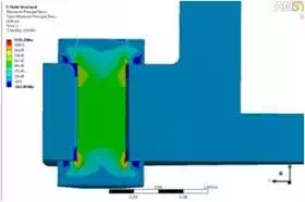
Figure 2: Bolt Preload Modeled Explicitly using Automated Constraint Equations – Maximum Principal Stress
3. “My bolt is non-standard and I would like to design the bolt such that the transfer of loading to the threads is more uniform than a standard bolt where the first couple threads carry all the load.”
(a) In addition to including the items listed above, explicit modeling of a threaded connection is required in this case, but can be greatly simplified by assuming an axisymmetric thread profile.
(b) Contact elements with or without friction should be modeled between the thread and nut and between the plates and bolt assembly if lift-off and onset of slippage need to be evaluated.
(c) A material model including plasticity is likely required in the thread regions since local yielding is common at the thread root.
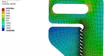
(d) Fillet radii need to be included as well along with a refined mesh at the contact interface and thread roots where stresses peak (Figure 3).
(e) A fracture mechanics evaluation might also be warranted to examine potential crack growth at the locations of peak tensile stresses.
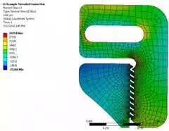
Figure 3: Hoop Stress in Detailed Threaded Connection Axisymmetric Analysis
There are many other scenarios that could be included in the finite element model of a bolted connection. Submodeling can often be used to develop more detailed bolt modeling with a local independent finite element model that accesses interpolated displacements boundary conditions from the global analysis. More details about modeling of bolted connections can be found in the 2012 NAFEMS publication “FEM Idealisation of Joints”, compiled by Peter Hopkins, ISBN 978-1-874376-72-9.
Check out our e-Learning session that details the modeling of bolted connections using ANSYS FEA software. An example of automating bearing loads is presented in this ANSYS User Group Paper.
Just remember to develop a clear objective prior to building your model and note that the simplest approach is often the best!