The very first Finite Element Method application was performed by my former professor, Raymond Clough at UC Berkeley in 1960. The application was a 2d analysis of a concrete (don’t you dare call it cement!) dam.
Figure 1. First Finite Element Method Mesh used to Analyze a Concrete Gravity Dam – 1960
Yet, more than 50 years later there is still no consensus on the best method to model concrete using finite elements. The current “best” method depends on the purpose of the calculation.Concrete is one of the most complex materials to model. Many research efforts and numerous papers have been published on modeling concrete, but no single method has been universally accepted. My personal recommendation is to choose the material model based on the analysis goal. The most common “concrete” categories for implicit finite element analyses are:
Linear Modeling of Concrete in Design
When the goal of structural reinforced concrete modeling is for design, a linear elastic material model can usually be applied where the modulus of elasticity for normal strength concrete is approximated by the following ACI 318 equations (where f’c is the concrete compressive strength):
 |
The stiffness of the reinforcement is excluded from the FE model since the goal of the design analysis is to calculate forces and moments and not detailed stresses. Forces and Moments from the linear analysis are used either in external (spreadsheets for example) or internal concrete design codes (like CivilFEM). These tools evaluate code-specific concrete design interaction diagrams to determine the required steel reinforcement to carry the internal section tensile forces, while also assuring the concrete can support the section compressive forces. Since the steel reinforcement area is usually much smaller than the concrete cross-section, there is no need to model the added stiffness from the reinforcement explicitly.
Nonlinear Modeling of Concrete
When subjected to small stresses and strains, concrete behaves as a linear-elastic material. However, beyond this threshold, concrete cracks in tension, creating a tension softening and it crushes in compression. Simulating this complex behavior is often required for earthquake loading, ultimate capacity, forensic or accident conditions. To capture the true concrete response, a microstructural representation has potential, but such modeling is not practical for large-scale structural analyses. Hence, a more phenomenological approach, represented by a nonlinear stress-strain response and failure surfaces, is recommended. The challenges include not only having a model that represents the material behavior adequately, but also one that is reliable and efficient since concrete cracking, crushing and softening is highly nonlinear.
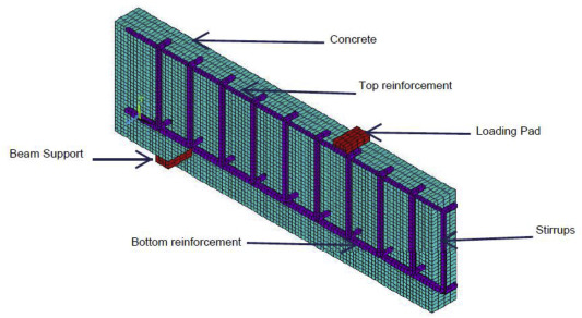
The smeared crack constitutive model approach (First developed by Rashid in 1968) is still one of the best. The formation of cracks is simulated by replacing the isotropic stiffness matrix by an orthotropic matrix upon crack formation. Stress normal to the crack direction is softened until it reaches a zero value. Once cracks form, they can close and reopen but their directions remain fixed. In large scale analyses, the stiffness of the rebar is best simulated with a smeared reinforcement element that utilizes a directional isotropic or kinematic hardening steel constitutive material law based on the reinforcement spacing. This can be automatically overlayed on the concrete element, for example ANSYS’ Solid65 element, or modeled externally, sharing nodes with the concrete element. Local cracking, aircraft impact events, or progressive collapse analyses can be accurately predicted with this modeling approach for large scale structures. I highly recommend running mesh sensitivity analyses when utilizing the smeared crack approach since it has been shown to be mesh sensitive. I also recommend performing a more explicit load stepping approach for these highly nonlinear cases, where a large number of intermediate solution steps, coupled with a displacement based convergence criterion can lead to the most efficient convergence.