
Understanding how structural parts interact and transfer load through mechanically fastened joints has long been a critical aspect of design. Even with the development of integrally machined parts, additive manufacturing, friction stir welding, and adhesive joining to name a few, many assemblies large or small still require some form of good old fashioned nuts and bolts.
To support the investigation of joint load transfer and the resultant material stresses in parts, many companies turn to finite element (FE) modeling and analysis to investigate the details. Engineers responsible for the structure have many pressing questions: Will my parts stay assembled together in their load environment? Will the fasteners or the parent material break first? Is the joint durable and can the parts sustain repeated load? These questions have to be answered!
Fortunately, we can accurately assess load transfer and material response through FE modeling of the representative parts. Of course, there are many approaches to this based on the focus of your analysis. There are different levels of pertinent analyses ranging from coarse mesh shell & beam modeling to sophisticated detailed 3D solid modeling.
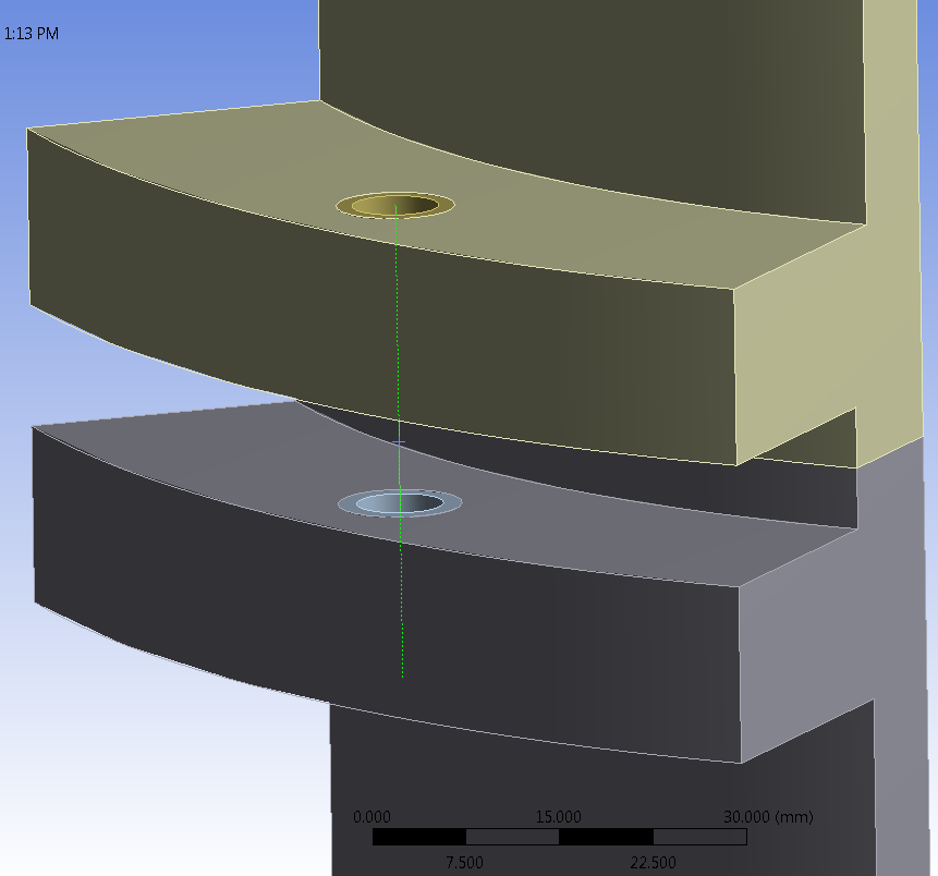
While there are merits to simple forms of FE modeling, I’ll expand on an approach I’ve found useful in a variety of applications in my course of FEA consulting: model the 3D assembly and fasteners with detailed solid finite elements. Most structures analyzed these days are modeled in a 3D CAD system to ensure the three “f”s : form, fit, and function of our parts. We can take advantage of the existing CAD assembly of those parts combined with parametrically defined hole size, fastener pattern, and addition of the 3D solid FE fastener in the model. Fortunately, with modern software capabilities we have automated 3D modeling tools (note Figure 1) to help us create these types of sophisticated assemblies and set up mating surfaces with contact describing the interaction between parts.
 |
Some investigative failure problems that I’ve worked on showed the importance of this approach. As one example, a part was prematurely cracking in a primary load transfer joint. However, the initiation of the crack was not at a hole edge or stress concentration location, as one may expect. The crack origin was originating under the head of the fastener and outside of the hole. After some detailed FEA of the scenario, there was a collective “aahh” by the customer while reviewing the FE results presentation that finally correlated the crack initiation site using the FE predictive tools. The 3D analysis captured the load transfer through frictional shear between the parts rather than pure bolt bearing. As shown in Figure 2, considering the same fastener clamp-up load, low values of friction resulted in peak stresses occurring at the edge of the hole. As the friction was increased, more load was transferred through shear between the plates and peak stresses occurred away from the hole. Fastener clamp-up, parent material stiffness, surface curvature, and bearing transfer were all captured by this 3D joint analysis method.
 |
Simpler tools based on analytical solutions often cannot capture some of these nuances of load transfer. I recommend taking a 3D modeling approach at critical joint areas to best understand the mechanisms of load transfer. Also, to assess uncertainties, sometimes you must bound the answers to the problem. For example, run solutions with small or large bolt preload and small or large friction coefficients in the analysis.
Using some automated postprocessing techniques with the 3D solid model can yield useful information regarding load transfer in your joint. In addition to investigating critical material stress results, the various contact pairs can be automatically queried to determine load per fastener through each layer in the material. This approach is helpful to plan out your most efficient joint load transfer.
With the additional accuracy comes the cost of performing the analysis. As with other general nonlinear analyses and larger problems, these runs will often take significant computing time. Also, with contact problems comes the challenge of obtaining problem convergence. Stay tuned for my next post for some tips in overcoming these challenges!