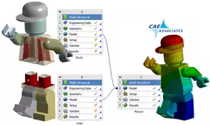
Finite Element models continue to grow in size and analyzing a large number of components in an assembly is becoming easy. Multiple CPU machines are common-place and, with the ability to mesh and solve in parallel, the actual work that the computer performs is continually scaling up. Yet, one of the main bottlenecks in the simulation process is how quickly aengineer can set up the simulation.
Having multiple FEA consulting analysts working on building the same model is nothing new; however it makes a lot of sense to do this regularly for large assemblies. It’s an easy way to decrease the lead time for obtaining the result. In order to accomplish this in an efficient manner, a common plan needs to be created and followed by all engineers ahead of time. Some of the important details that should be included a modular simulation plan are provided below:
BREAK UP THE ASSEMBLY: The goal of having multiple engineers build one finite element model is to arrive at the finished assembly model faster. Therefore; each individual needs to work on one or a subset of components in the assembly, and at the end, all engineers will save their individual databases and assemble them together to create the full assembly model.
PART ALIGNMENT: Each engineer should have their part built in the correct “modeling space” so that all the parts once assembled will align properly. A master file relating all the positions of all the components could also be used when combining the models; but this can easily be avoided in the upfront planning.
TAGGED PROPERTIES: A set of identifying feature/ attribute names (i.e. components, named selections, tagged surfaces, etc.) should be built into each component database. These common and consistent names across all databases in the assembly should be used to identify material properties, boundary conditions, loads and contact pairs. Depending upon the software, it might be easier to assign materials, for example, within each database. In other FEA software, it might be easier to use the named attributes within each database to assign the materials once combined into the full assembly. Whichever approach is used, these properties saved into each individual database must transfer into the main assembly and will be used to define their respective conditions.
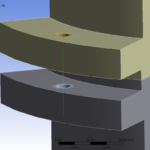
ASSEMBLY CONTACT: All the individual databases will eventually be assembled and connected together in the full model. The use of bonded contact will be of great importance in assembly modeling as it allows for all the components to be meshed independently by each engineer, without having to know what the mesh on all the other components will look like. Some FEA software, like ANSYS Mechanical, has the built in capability to automatically recognize mating surfaces and create a bonded contact pair. If this capability is not available when combining the full assembly, this is when the consistent naming of surfaces facilitates manually setting up the contact between components. For example, two flanges each meshed and saved into two different databases by two different FEA consulting engineers. The two flanges are to be bonded together in the full assembly. The surface on one flange could be named “bond_A1_to_B1” and in the other database the mating surface is named “bond_B1_to_A1”. Listing all the contacts that need to be bonded together in a master file will make it easy to automate the contact creation with a short script.
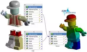
The above figure is an illustration of two independent databases that are meshed, setup with boundary conditions, loads, material properties, named selections and contacts. Once the bonded contact pair is defined between the identified surfaces in the assembled model, it’s ready to solve.
MODEL DOCUMENTATION: Lastly, all the details of each database should be documented by the engineer throughout the setup process. This document will allow for all the FEA consulting engineers to keep track of what’s in each model and how they’ll all come together once assembled. Clear and consistent communication between all engineers is critically important for the final model to be assembled accurately.
This modular simulation system technique for creating a large assembly model also makes it possible and very easy to swap in and out new components without affecting the rest of the assembly. This modular simulation approach scales very well when used in a design of experiments (DOE analyses) to perform quick design changes on the component level and determine the full system’s response to the new design.