
Many machines depend on one rotating component driving another. An electric motor may need to turn a pump, a turbine may drive a generator, or a gearbox may transmit torque to a conveyor, fan, compressor, or machine spindle.
At first glance, connecting two shafts may seem simple: just join them together and let them rotate as one.
In practice, it is more complicated.
Two shafts are rarely aligned with absolute perfection. Their centerlines may be slightly offset, their angles may differ, the shafts may move as temperatures change, or machine foundations may settle over time. If the shafts were connected by a perfectly rigid link, even a small misalignment could create large forces on bearings, seals, and shafts. ⚠️
This is why machines use shaft couplings.
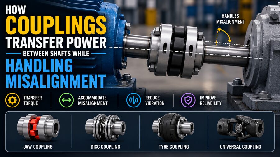
A coupling transfers rotational power from one shaft to another while also accommodating some combination of angular, parallel, and axial misalignment.
The basic principle is:
Transmit torque efficiently while preventing small alignment errors from becoming damaging mechanical loads. 🔩🔄
🔗 1. What Is a Shaft Coupling?
A shaft coupling is a mechanical device placed between two rotating shafts.
Its primary job is to transfer:
- Torque
- Rotational speed
- Mechanical power
from the driving shaft to the driven shaft.
For example:
Electric Motor → Coupling → Pump
The motor creates torque.
The coupling transfers that torque.
The pump shaft receives it and begins rotating.
A coupling may look like a relatively small component compared with the motor or driven machine, but its role is critical.
If it fails, power transmission stops immediately.
⚡ 2. How a Coupling Transfers Torque
Torque is the twisting force that causes a shaft to rotate.
If a motor produces torque T at angular velocity ω, the mechanical power being transmitted is:
P = T × ω
where:
P= powerT= torqueω= angular velocity
A coupling must transmit that torque from one hub to the other.
Depending on the design, torque may pass through:
- Bolts
- Gear teeth
- Flexible elastomer
- Metallic discs
- Grid elements
- Jaw inserts
- Rigid flanges
The coupling must be strong enough to handle both normal operating torque and temporary overloads such as startup or sudden load changes. 💪
📐 3. Why Perfect Shaft Alignment Is Difficult
In theory, two connected shafts could be positioned so their centerlines are perfectly coincident.
In reality, many factors make this difficult.
Misalignment can result from:
- Installation tolerances
- Foundation movement
- Bearing wear
- Thermal expansion
- Pipe strain
- Machine vibration
- Manufacturing tolerances
- Structural deflection
Even machines that are carefully aligned during installation may shift after operating for hours and heating up.
This is why couplings are often designed with flexibility.
However, a coupling should not be used as an excuse for poor alignment.
The machine should still be aligned as accurately as practical. 🎯
↔️ 4. Parallel Misalignment
Parallel misalignment occurs when the two shafts are parallel but their centerlines are offset.
Imagine two perfectly horizontal shafts where one is positioned a few millimeters higher than the other.
Their directions match, but their axes do not lie on the same line.
A flexible coupling can accommodate limited parallel offset by allowing its flexible element to deform or articulate during rotation.
Without this flexibility, the coupling would force the shafts toward one another.
That could create excessive radial loads on the bearings.
📐 5. Angular Misalignment
Angular misalignment occurs when the two shafts meet at a small angle.
Instead of their centerlines being parallel, they point slightly toward or away from each other.
As the coupling rotates, the relative geometry continuously changes.
Flexible couplings handle this by allowing their internal elements to bend, pivot, or slide.
For example, a disc coupling may flex its thin metallic discs slightly.
A gear coupling allows crowned gear teeth to articulate.
An elastomeric coupling deforms its flexible insert.
Each design uses a different mechanical method to accommodate the same basic problem. 🔄
↕️ 6. Axial Movement
Shafts can also move toward or away from each other along their own axes.
This is called axial displacement or end float.
Axial movement may result from:
- Thermal expansion
- Bearing clearance
- Rotor movement
- Equipment loading
- Installation tolerance
Certain couplings can absorb limited axial movement.
Others are designed to be axially rigid.
Selecting the wrong coupling can create unwanted thrust loads on bearings.
Therefore, axial behavior must be considered during coupling selection. 🧭
🧱 7. Rigid Couplings Provide Almost No Misalignment Capacity
A rigid coupling connects two shafts with very little flexibility.
Examples include:
- Sleeve couplings
- Clamp couplings
- Rigid flange couplings
Rigid couplings can transmit torque efficiently and maintain precise shaft positioning.
However, they require very accurate alignment.
They are appropriate when:
- Shafts are already well aligned
- Structural movement is minimal
- Precise rotational positioning is important
- The shafts effectively need to behave as one continuous shaft
Because rigid couplings do not absorb much misalignment, errors are transferred directly into the connected machinery.
🟠 8. Elastomeric Couplings Use Flexible Material
One popular flexible coupling uses an elastomer such as rubber or polyurethane.
Examples include:
- Jaw couplings
- Tire couplings
- Sleeve-type elastomeric couplings
A flexible element is installed between two metallic hubs.
When torque passes through the coupling, the elastomer deforms slightly.
This allows the coupling to absorb:
- Small misalignment
- Shock loads
- Vibration
- Torsional oscillations
The elastomer also helps isolate vibration between the driving and driven machines.
This makes elastomeric couplings popular in pumps, fans, compressors, and general industrial equipment. 🟠⚙️
🦷 9. Jaw Couplings Transfer Torque Through an Insert
A common jaw coupling consists of two hubs with projecting jaws.
Between them sits an elastomeric insert often called a spider.
The motor-side hub pushes against the spider.
The spider then transfers torque into the driven-side hub.
Because the insert is flexible, it can tolerate small misalignment and reduce shock transmission.
Jaw couplings are:
- Compact
- Relatively inexpensive
- Easy to maintain
- Widely available
However, the elastomer has limits on temperature, torque, speed, and chemical exposure.
⚙️ 10. Gear Couplings Use Meshing Teeth
A gear coupling uses toothed hubs and toothed sleeves.
The teeth transmit torque similarly to gears.
However, the teeth are often shaped to allow small angular movement.
Gear couplings can handle very high torque in a compact size.
They are commonly found in:
- Heavy industrial drives
- Steel mills
- Large pumps
- Compressors
- Turbines
- Mining equipment
Many gear couplings require lubrication because the teeth move slightly relative to one another during operation.
Poor lubrication can lead to:
- Wear
- Fretting
- Tooth damage
- Overheating
So maintenance is important. 🛢️
🌀 11. Grid Couplings Use a Flexible Steel Spring
A grid coupling uses a serpentine metallic grid that fits into grooves in two hubs.
Torque passes through the grid from one hub to the other.
The grid can flex slightly, allowing the coupling to accommodate misalignment and absorb shock.
Grid couplings are useful in applications with:
- High torque
- Moderate shock loads
- Industrial duty
- Repeated starts and stops
They can also provide some torsional damping.
However, like gear couplings, many grid couplings require proper lubrication and periodic inspection.
🥏 12. Disc Couplings Use Thin Metallic Plates
A disc coupling uses one or more packs of thin metal discs.
The discs are bolted between hubs and sometimes an intermediate spacer.
Torque is transmitted through tension and compression in the discs.
The discs can flex slightly to accommodate angular and axial misalignment.
Disc couplings are attractive because they can operate:
- Without lubrication
- At high speeds
- At elevated temperatures
- With high torsional stiffness
They are often used in compressors, turbines, pumps, and other high-performance rotating machinery. 🚀
Because the discs are metallic, they do not provide as much torsional damping as many elastomeric designs.
🪢 13. Oldham Couplings Handle Parallel Offset Well
An Oldham coupling consists of two hubs and a center disc.
The center disc engages slots in the two hubs at right angles.
As the shafts rotate, the center disc slides between the hubs.
This motion allows the coupling to handle significant parallel misalignment while transmitting torque.
Oldham couplings are especially useful in:
- Motion-control equipment
- Robotics
- Small machinery
- Precision drives
They are not usually selected for extremely high-power heavy industrial service, but their geometry makes them elegant solutions for offset shafts.
🧿 14. Universal Joints Handle Larger Angles
A universal joint is sometimes considered separately from conventional couplings, but it serves a related purpose.
It can transmit torque between shafts that meet at a significant angle.
Universal joints are found in:
- Vehicle drivetrains
- Agricultural equipment
- Steering systems
- Industrial shafts
A single universal joint can introduce nonuniform output speed when operating at an angle.
Using two joints with the correct geometry can compensate for this effect.
Universal joints handle angular misalignment far beyond what many flexible couplings can tolerate.
🛡️ 15. Couplings Protect Bearings From Misalignment Forces
Bearings are designed to support rotating shafts.
They can handle certain radial and axial loads.
But excessive shaft misalignment can add unwanted forces.
A rigid connection between misaligned shafts may cause:
- Bearing overheating
- Premature bearing failure
- Seal wear
- Shaft bending
- Vibration
- Coupling damage
Flexible couplings reduce these loads by allowing controlled movement.
This helps the machines operate more smoothly and can significantly extend component life. 🔧
🌡️ 16. Thermal Growth Is a Major Alignment Challenge
Large machines change dimensions as their temperature changes.
A pump may be aligned to a motor while both are cold.
After startup, the pump casing, motor frame, bearings, and foundation heat up.
Thermal expansion may move the shaft centerlines.
This is called thermal growth.
Engineers sometimes deliberately align machines slightly offset while cold so they become correctly aligned at operating temperature.
The coupling must tolerate the remaining movement.
This is especially important in:
- Steam turbines
- Compressors
- Hot oil pumps
- High-temperature process machinery
🎵 17. Couplings Can Influence Torsional Vibration
Rotating systems do not always rotate smoothly.
Torque may fluctuate due to:
- Reciprocating engines
- Compressors
- Gear tooth engagement
- Electrical disturbances
- Sudden load changes
These fluctuations can cause torsional vibration, where shafts twist back and forth slightly.
Coupling stiffness affects how these vibrations travel through the drivetrain.
An elastomeric coupling can absorb some torsional energy.
A highly rigid metallic coupling may transmit more vibration.
Engineers sometimes perform torsional analysis to ensure the coupling does not create dangerous resonance conditions. 📉
🚦 18. Startup Torque Can Be Much Higher Than Normal Torque
A coupling must not be sized only for steady-state operating load.
During startup, an electric motor may produce substantially higher torque.
Driven equipment can also resist acceleration because of inertia.
Shock loads may occur when:
- Conveyors start loaded
- Crushers encounter material
- Pumps experience hydraulic transients
- Gearboxes change load suddenly
Coupling selection therefore uses service factors that account for application severity.
A coupling that works continuously at steady load may fail quickly if repeated starts are ignored.
📊 19. Torque Rating Is Only One Selection Parameter
Engineers consider many factors when selecting a coupling.
These include:
- Continuous torque
- Peak torque
- Shaft diameter
- Rotational speed
- Angular misalignment
- Parallel misalignment
- Axial movement
- Temperature
- Vibration
- Environment
- Lubrication requirements
- Maintenance access
- Required torsional stiffness
A coupling with enormous torque capacity may still be unsuitable if it cannot handle the expected misalignment.
Selection must therefore consider the whole operating system. ⚖️
📏 20. Misalignment Limits Must Not Be Exceeded
Flexible couplings are not infinitely flexible.
Manufacturers specify maximum allowable values for:
- Angular misalignment
- Parallel offset
- Axial displacement
Operating close to those limits can reduce coupling life.
This is why good practice is to align equipment much more accurately than the absolute maximum coupling capacity.
The coupling should handle normal thermal and operational movement—not compensate for careless installation.
🔍 21. Laser Alignment Improves Coupling Life
Modern rotating equipment is often aligned using laser shaft alignment systems.
Sensors are mounted on the two shafts.
As the shafts are rotated, the system measures relative position.
Software calculates corrections such as:
- Move motor left
- Raise front feet
- Lower rear feet
- Adjust horizontal offset
Laser systems can achieve high accuracy and reduce installation time.
Better alignment leads to:
- Lower vibration
- Reduced bearing loads
- Longer seal life
- Lower coupling stress
- Improved energy efficiency
Even flexible couplings benefit from precise alignment. 🎯
🦶 22. Soft Foot Can Cause Misalignment
Before shaft alignment is finalized, engineers may check for soft foot.
Soft foot occurs when one machine foot does not sit evenly on its base.
When mounting bolts are tightened, the machine frame can distort.
This can shift the shaft and create alignment problems.
Correcting soft foot may involve:
- Cleaning base surfaces
- Adjusting shims
- Repairing distorted feet
- Correcting foundation problems
Ignoring soft foot can make precise shaft alignment impossible.
🌀 23. Coupling Balance Matters at High Speed
At high rotational speed, even a small mass imbalance can create significant centrifugal force.
Large high-speed couplings may therefore require precision balancing.
An unbalanced coupling can cause:
- Vibration
- Bearing loads
- Fatigue
- Noise
- Reduced equipment life
High-speed turbine and compressor applications often impose much stricter balance requirements than low-speed industrial drives.
🔒 24. Some Couplings Provide Fail-Safe Behavior
Certain coupling designs are chosen so that torque transmission can continue temporarily even if a flexible element is damaged.
Others intentionally disconnect when overloaded.
For example, a torque-limiting coupling may slip or release if torque exceeds a safe threshold.
This can protect expensive machinery from overload.
In other applications, a fail-safe coupling may continue transmitting reduced torque long enough for controlled shutdown.
The required failure behavior depends on the machine’s safety philosophy. 🛡️
🛠️ 25. Maintenance Depends on Coupling Type
Different couplings require different levels of maintenance.
An elastomeric coupling may require periodic insert inspection.
A gear coupling may require lubrication.
A grid coupling may need grease replacement.
A disc coupling may need visual checks for cracked or distorted plates.
Common inspection items include:
- Wear
- Cracks
- Loose bolts
- Lubricant condition
- Corrosion
- Abnormal noise
- Excessive vibration
Couplings are often enclosed by guards, so inspection planning is important.
🦺 26. Coupling Guards Are Essential for Safety
A rotating coupling can be extremely dangerous if exposed.
Loose clothing, tools, or body parts could become caught in rotating components.
Industrial installations therefore use coupling guards.
A proper guard prevents accidental contact while still allowing ventilation and maintenance access where needed.
Safety regulations often require guarding of rotating power-transmission equipment.
The coupling may be mechanically small, but at thousands of revolutions per minute it stores and transmits substantial energy. ⚠️
🧠 27. Flexible Does Not Mean Loose
A common misunderstanding is that a flexible coupling must feel soft or sloppy.
Many flexible couplings are actually very torsionally stiff.
They allow carefully controlled movement in specific directions while continuing to transmit torque precisely.
For example, a disc coupling can tolerate angular misalignment through disc bending while remaining highly rigid in torsion.
This is important in systems where accurate rotational positioning matters.
Flexibility is therefore directional and engineered—not uncontrolled movement.
🏭 28. Common Industrial Applications
Shaft couplings appear throughout industry.
They connect:
Motors to pumps 💧
Motors to fans 🌬️
Engines to gearboxes 🚜
Turbines to generators ⚡
Gearboxes to conveyors 📦
Motors to compressors 🏭
Servo motors to precision mechanisms 🤖
The correct coupling for a small servo motor may be completely different from the one used between a megawatt turbine and generator.
Yet the fundamental role remains the same.
🔄 29. A Typical Power-Transfer Path
Consider a motor driving a centrifugal pump.
The process is:
1. Electrical energy powers the motor. ⚡
2. The motor creates torque at its shaft.
3. The motor-side coupling hub receives that torque.
4. The flexible coupling element transfers it across the shaft gap.
5. The pump-side hub transfers torque to the pump shaft.
6. The pump impeller rotates and moves fluid. 💧
At the same time, the coupling continuously accommodates small shaft movements.
The machine therefore transfers power while avoiding unnecessary mechanical stress.
🧩 30. The Core Engineering Idea
A shaft coupling has two jobs that may seem contradictory.
It must be rigid enough in rotation to transmit torque.
Yet it must be flexible enough in selected directions to tolerate misalignment.
Good coupling design achieves both.
The coupling resists relative twisting strongly enough to deliver power while allowing limited bending, sliding, or elastic deformation where needed.
That balance is what makes flexible couplings so useful.
🏁 Conclusion
Shaft couplings are essential components in rotating machinery because they allow one shaft to transfer power to another without requiring impossible geometric perfection.
The driving shaft applies torque to one side of the coupling.
The coupling transfers that torque through gears, discs, elastomers, grids, jaws, or other mechanical elements.
The driven shaft then receives the power and turns the connected machine. ⚙️🔄
At the same time, flexible coupling designs can accommodate limited:
Angular misalignment 📐
Parallel misalignment ↔️
Axial movement ↕️
This prevents small installation errors, thermal growth, vibration, and structural movement from producing excessive loads on bearings, seals, and shafts.
Different coupling designs solve the problem in different ways. Elastomeric couplings deform, gear couplings articulate through toothed interfaces, disc couplings flex metallic plates, and Oldham couplings use sliding geometry.
The correct choice depends on torque, speed, misalignment, temperature, vibration, maintenance requirements, and the behavior of the entire drivetrain.
A coupling may look like a simple connector between two shafts, but it performs a sophisticated mechanical balancing act:
transfer rotational power firmly while allowing just enough controlled movement to keep the connected machines healthy. 🔩⚙️💪