Grey cast iron is characterised by its graphitic microstructure, which causes fractures of the material to have a grey appearance. It is the most commonly used cast iron and the most widely used cast material based on weight. Most cast irons have a chemical composition of 2.5–4.0% carbon, 1–3% silicon, and the remainder is iron. Grey cast iron has less tensile strength and shock resistance than steel, but its compressive strength is comparable to low and medium carbon steel.
Cast iron is iron or a ferrous alloy which has been heated until it liquefies, and is then poured into a mould to solidify. It is usually made from pig iron. The alloy constituents affect its colour when fractured: white cast iron has carbide impurities which allow cracks to pass straight through. Grey cast iron has graphite flakes which deflect a passing crack and initiate countless new cracks as the material breaks. Carbon (C) and silicon (Si) are the main alloying elements, with the amount ranging from 2.1–4 wt% and 1–3 wt%, respectively. Iron alloys with less carbon content are known as steel. While this technically makes these base alloys ternary Fe–C–Si alloys, the principle of cast iron solidification is understood from the binary iron–carbon phase diagram. Since the compositions of most cast irons are around the eutectic point of the iron–carbon system, the melting temperatures closely correlate, usually ranging from 1,150 to 1,200 °C (2,100 to 2,190 °F), which is about 300 °C (572 °F) lower than the melting point of pure iron. Cast iron's properties are changed by adding various alloying elements, or alloyants. Next to carbon,…
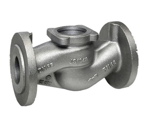
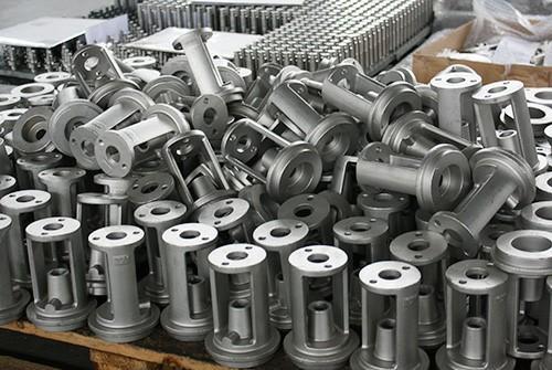
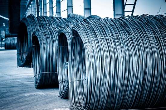
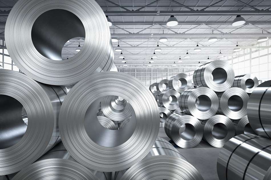
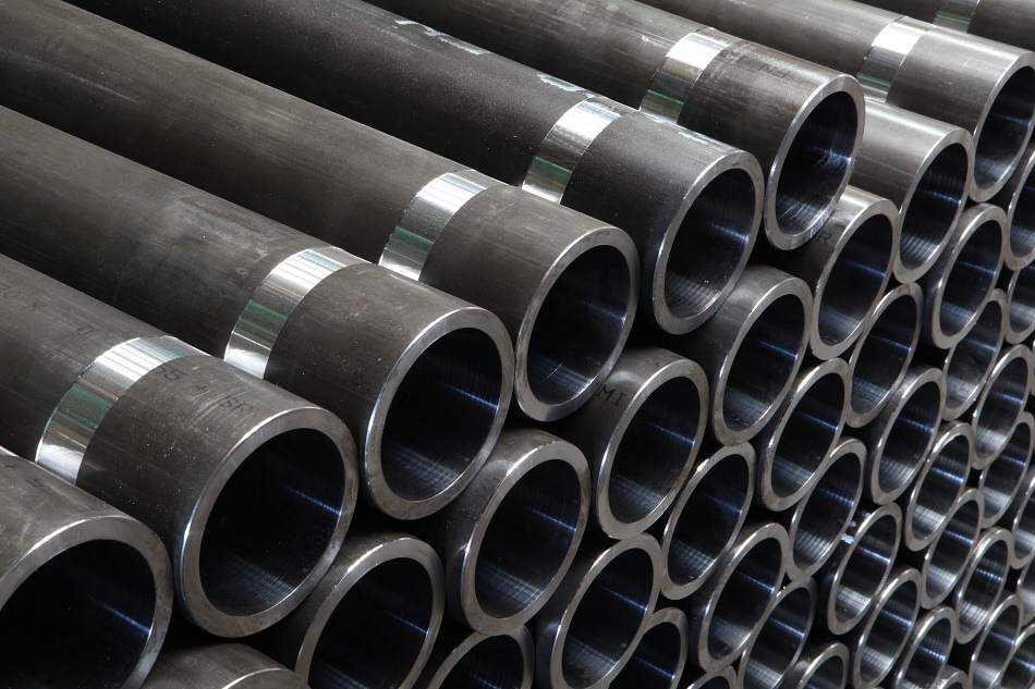
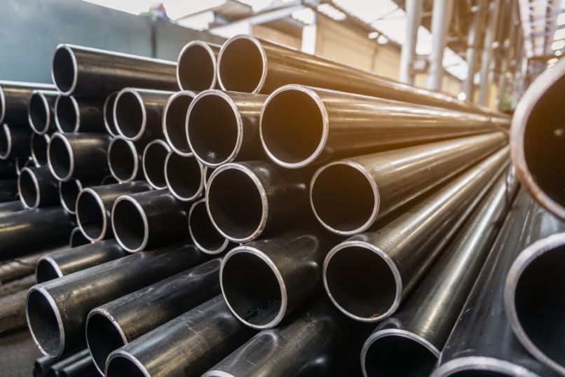
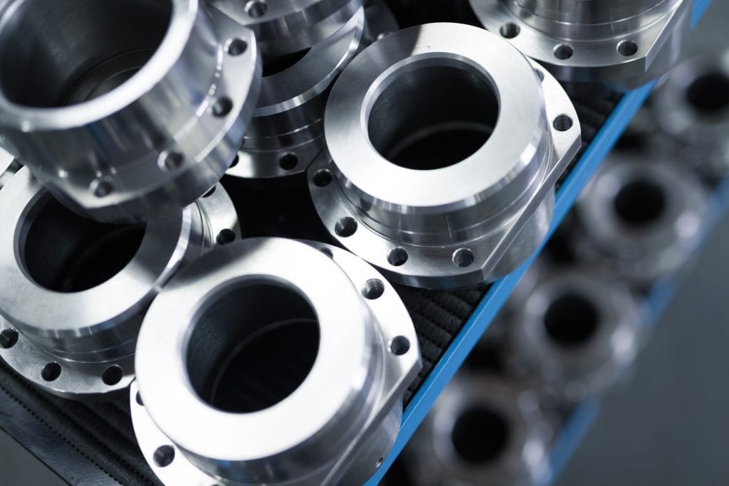
• Long/Tubular Products include bars and rods, rails, wires, angles, pipes, and shapes and sections. These products are commonly used in the automotive and construction sectors. • Flat Products include plates, sheets, coils and strips. These materials are mainly used in automotive parts, appliances, packaging, shipbuilding, and construction. • Other Products include valves, fittings, and flanges and are mainly used as piping materials.
Alloy steel is steel that is alloyed with a variety of elements in total amounts between 1.0% and 50% by weight to improve its mechanical properties. Alloy steels are broken down into two groups: low-alloy steels and high-alloy steels. The difference between the two is somewhat arbitrary: Smith and Has hemi define the difference at 4.0%, while Degarmo, et al., define it at 8.0%. Most commonly, the phrase "alloy steel" refers to low-alloy steels. Types: According to the World Steel Association, there are over 3,500 different grades of steel, encompassing unique physical, chemical and environmental properties. In essence, steel is composed of iron and carbon, although it is the amount of carbon, as well as the level of impurities and additional alloying elements that determines the properties of each steel grade. The carbon content in steel can range from 0.1-1.5%, but the most widely used grades of steel contain only 0.1-0.25% carbon. Elements such as manganese, phosphorus and sulphur are found in all grades of steel, but, whereas manganese …
Carbon steel is steel in which the main interstitial alloying constituent is carbon in the range of 0.12–2.0%. The American Iron and Steel Institute (AISI) defines carbon steel as the following: "Steel is considered to be carbon steel when no minimum content is specified or required for chromium, cobalt, molybdenum, nickel, niobium, titanium, tungsten, vanadium or zirconium, or any other element to be added to obtain a desired alloying effect; when the specified minimum for copper does not exceed 0.40 percent; or when the maximum content specified for any of the following elements does not exceed the percentages noted: manganese 1.65, silicon 0.60, copper 0.60. Types: Carbon steel is broken down into four classes based on carbon content: Mild and low-carbon steel Mild steel also known as plain-carbon steel, is the most common form of steel because its price is relatively low while it provides material properties that are acceptable for many applications, more so than iron. Low-carbon steel contains approximately…
Isothermal Transformation Diagrams We use as an example the cooling of an eutectoid alloy (0.8 % C) from the austenite (γ- phase) to pearlite, that contains ferrite (α) plus cementite (Fe3C or iron carbide). When cooling proceeds below the eutectoid temperature (727 oC) nucleation of pearlite starts. The S-shaped curves (fraction of pearlite vs. log. time, fig. 10.3) are displaced to longer times at higher temperatures showing that the transformation is dominated by nucleation (the nucleation period is longer at higher temperatures) and not by diffusion (which occurs faster at higher temperatures). The family of S-shaped curves at different temperatures can be used to construct the TTT (Time- Temperature-Transformation) diagrams For these diagrams to apply, one needs to cool the material quickly to a given temperature To before the transformation occurs, and keep it at that temperature over time. The horizontal line that indicates constant temperature To intercepts the…
(TTT) diagrams measure the rate of transformation at a constant temperature. In other words a sample is austenitised and then cooled rapidly to a lower temperature and held at that temperature whilst the rate of transformation is measured, for example by dilatometry. Obviously a largenumber of experiments is required to build up a complete TTT diagram. • An increase in carbon content shifts the TTT curve to the right (this corresponds to an increase in hardenability as it increases the ease of forming martensite - i.e. the cooling rate required to attain martensite is less severe). • An increase in carbon content decreases the martensite start temperature. • An increase in Mo content shifts the TTT curve to the right and also separates the ferrite + pearlite region from the bainite region making the attainment ofa bainitic structure more controllable.
Alloying strengthens metals by hindering the motion of dislocations. Thus, the strength of Fe–C alloys increase with C content and also with the addition of other elements.
The eutectoid composition of austenite is 0.8 wt %. When it cools slowly it forms perlite, a lamellar or layered structure of two phases: α-ferrite and cementite (Fe3C). Hypoeutectoid alloys contain proeutectoid ferrite plus the eutectoid pearlite. Hypereutectoid alloys contain proeutectoid cementite plus pearlite. Since reactions below the eutectoid temperature are in the solid phase, the equilibrium is not achieved by usual cooling from austenite
- Hypoeutectoid steels (carbon content from 0 to 0.83%) consist of primary (proeutectoid) ferrite (according to the curve A3) and Pearlite. - Eutectoid steel (carbon content 0.83%) entirely consists of Pearlite. - Hypereutectoid steels (carbon content from 0.83 to 2.06%) consist of primary (proeutectoid) cementite (according to the curve ACM) and Pearlite. - Cast irons (carbon content from 2.06% to 4.3%) consist of cementite ejected from austenite according to the curve ACM , Pearlite and transformed ledeburite (ledeburite in which austenite transformed to pearlite). When the liquid of eutectic composition is cooled, at or below eutectic temperature this liquid transforms simultaneously into two solid phases (two terminal solid solutions, represented by αand β). This transformation is…