Posted inMaterial Science
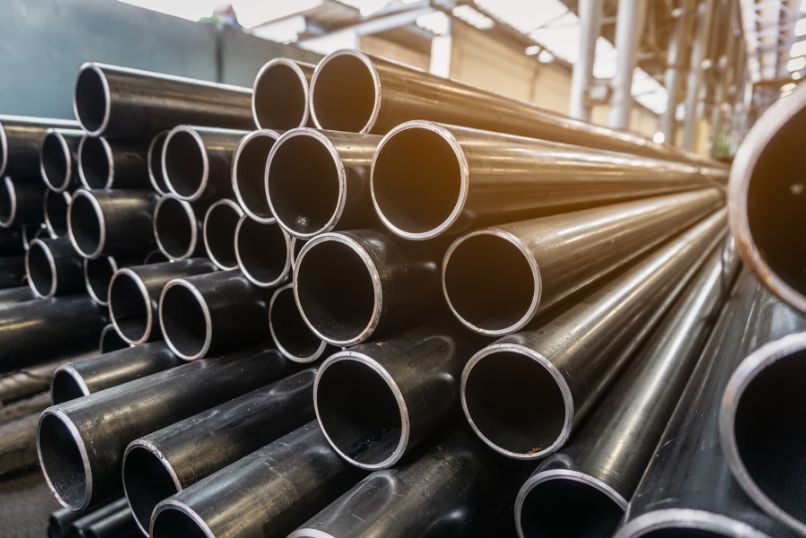
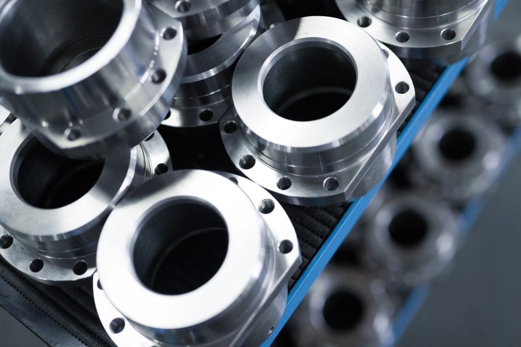
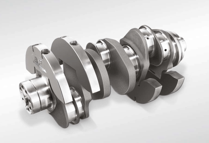
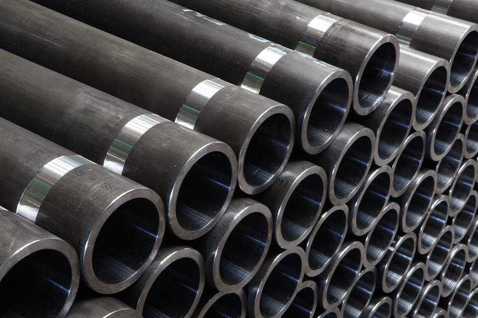
Various types of carbon steel
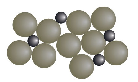
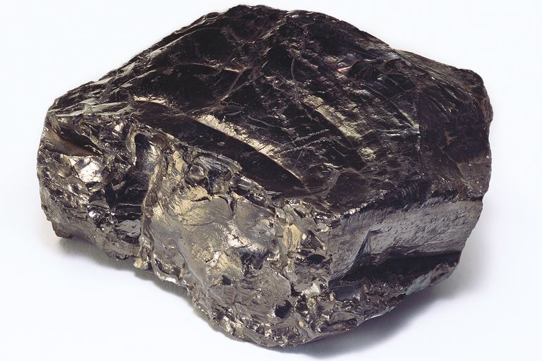
Carbon steel is steel in which the main interstitial alloying constituent is carbon in the range of 0.12–2.0%. The American Iron and Steel Institute (AISI) defines carbon steel as the following: "Steel is considered to be carbon steel when no minimum content is specified or required for chromium, cobalt, molybdenum, nickel, niobium, titanium, tungsten, vanadium or zirconium, or any other element to be added to obtain a desired alloying effect; when the specified minimum for copper does not exceed 0.40 percent; or when the maximum content specified for any of the following elements does not exceed the percentages noted: manganese 1.65, silicon 0.60, copper 0.60. Types: Carbon steel is broken down into four classes based on carbon content: Mild and low-carbon steel Mild steel also known as plain-carbon steel, is the most common form of steel because its price is relatively low while it provides material properties that are acceptable for many applications, more so than iron. Low-carbon steel contains approximately…