In ionic materials, the band gap is too large for thermal electron promotion. Cation vacancies allow ionic motion in the direction of an applied electric field, this is referred to as ionic conduction. High temperatures produce more vacancies and higher ionic conductivity. At low temperatures, electrical conduction in insulators is usually along the surface, due to the deposition of moisture that contains impurity ions.
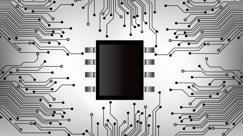
A semiconductor diode is made by the intimate junction of a p-type and an n-typesemiconductor (an n-p junction). Unlike a metal, the intensity of the electrical current that passes through the material depends on the polarity of the applied voltage. If the positive side of abattery is connected to the p-side, a situation called forward bias, a large amount of current can flow since holes and electrons are pushed into the junction region, where they recombine (annihilate). If the polarity of the voltage is flipped, the diode operates under reverse bias. Holes andelectrons are removed from the region of the junction, which therefore becomes depleted of carriers and behaves like an insulator. For this reason, the current is very small under reverse bias. The asymmetric current-voltage characteristics of diodes is used to convert alternating current into direct current. This is called rectification. A p-n-p junction transistor contains two diodes back-to-back. The central region is very thin and is called the base. A small voltage applied to the base has a large effect on the current passing through the transistor, and this can be used to amplify electrical signals (Fig. 19.22). Anothercommon device is the MOSFET transistor where a gate serves the function of the base in a junction transistor. Control of the current through the transistor is by means of the electric field induced by the gate, which is isolated electrically by an oxide layer.
Intrinsic Semiconductor Semiconductors can be intrinsic or extrinsic. Intrinsic means that electrical conductivity does not depend on impurities, thus intrinsic means pure. In extrinsic semiconductors the conductivity depends on the concentration of impurities. Conduction is by electrons and holes. In an electric field, electrons and holes move in opposite direction because they have opposite charges. In an intrinsic semiconductor, a hole is produced by the promotion of each electron to the conduction band. Thus: n = p Extrinsic…
The resistivity then depends on collisions. Quantum mechanics tells us that electrons behave like waves. One of the effects of this is that electrons do not scatter from a perfect lattice. They scatter by defects, which can be: - atoms displaced by lattice vibrations - vacancies and interstitials - dislocations, grain boundaries - impurities One can express the total resistivity ρtot by the Matthiessen rule, as a sum of resistivities due to thermal vibrations, impurities and dislocations. Fig. 19.8 illustrates how the resistivity increases with temperature, with deformation, and with alloying..
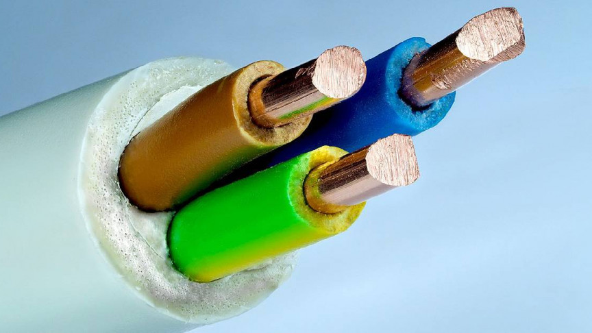
Electronic and Ionic Conduction In metals, the current is carried by electrons, and hence the name electronic conduction. In ionic crystals, the charge carriers are ions, thus the name ionic conduction. Energy Band Structures in Solids When atoms come together to form a solid, their valence electrons interact due to Coulomb forces, and they also feel the electric field produced by their own nucleus and that of the other atoms. In addition, two specific quantum mechanical effects happen. First, by Heisenberg's uncertainty principle, constraining the electrons to a small volume raises their energy, this is called promotion. The second effect, due to the Pauli Exclusion Principle, limits the number of electrons that can have the same property (which include the energy). As a result of all these effects, the valence electrons of atoms form wide valence bands when they form a solid. The bands are separated by gaps, where electrons cannot exist. The precise location of the bands and band gaps depends on the type…
Recording data onto a disk has obvious advantages with respect to access times, as the head can readily be moved to the appropriate place on the disk whereas a tape would need to be rewound or advanced. There are two types of disk: floppy and hard. The principles of manufacturing and recording on floppy disks are very similar to that of particulate magnetic tape, i.e. the same particulate materials on a plastic substrates. Hard disk drives are formed on a rigid substrate, usually aluminium, which is around 2mm thick. On to the substrate are deposited several layers: an under layer to help adhesion (~10nm nickel phosphide); a layer of chromium (5-10nm) to control orientation and grain size of magnetic layer; the magnetic layer (50nm PtCo with various additions of Ta, P, Ni, Cr); a protective overcoat (e.g. 10-20nm zirconia) and finally lubricant to reduce friction and wear of the disk (e.g. a monolayer of long chain fluorocarbons). The magnetic layer forms a cellular structure of Co-rich magnetic cells in a non-magnetic matrix. These cells act just like particulate recording media but on…
Magnetic tapes are extensively used for recording audio and video signals, although it is unclear how long this technology will continue to be used with the rising popularity of the digital versatile disk (DVD). Tapes can be made with either a particulate media adhered to a plastic substrate or a metal evaporated (ME) film on the substrate. The magnetic layer on a particulate tape is only 40% magnetic material whereas ME tapes have a 100% magnetic layer. Therefore, ME tapes give better quality recording, but they are more time consuming to produce and are more expensive. Particulate tapes are much cheaper and hence account for the majority of magnetic tapes.
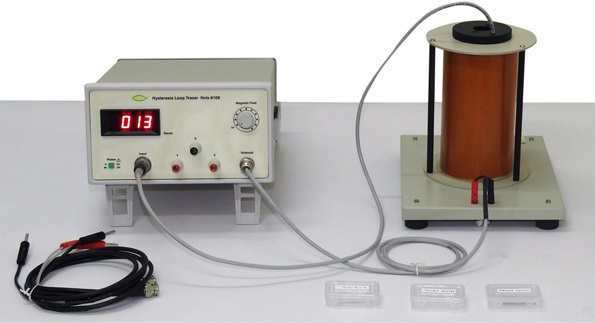
A great deal of information can be learned about the magnetic properties of a material by studying its hysteresis loop. A hysteresis loop shows the relationship between the induced magnetic flux density (B) and the magnetizing force (H). It is often referred to as the B-H loop. An example hysteresis loop is shown below. The loop is generated by measuring the magnetic flux of a ferromagnetic material while the magnetizing force is changed. A ferromagnetic material that has never been previously magnetized or has been thoroughly demagnetized will follow the dashed line as H is increased. As the line demonstrates, the greater the amount of current applied (H+), the stronger the magnetic field in the component (B+). At point "a" almost all of the magnetic domains are aligned and an additional increase in the magnetizing force will produce very little increase in magnetic flux. The material has reached the point of magnetic saturation. When H is reduced to zero, the curve will move from point "a" to point "b." At this point, it can be seen that some magnetic flux remains in the material even though the magnetizing force is zero. This is referred to as the point of retentivity on the graph and indicates the remanence or level of residual magnetism in the material. (Some of the magnetic domains remain aligned but some…
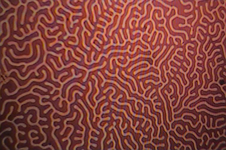
Any ferromagnetic or ferromagnetic material that is at a temperature below Tc is composed of small-volume regions in which there is a mutual alignment in the same direction of all magnetic dipole moments. Such a region is called a domain, and each one is magnetized to its saturation magnetization. Adjacent domains are separated by domain boundaries or walls across which the direction of magnetization gradually changes. Normally, domains are microscopic in size and for a polycrystalline specimen, each grain may consist of a single domain. Thus, in a microscopic piece of material, there will be large number of domains and all may have different magnetization orientations
Temperature can also influence the magnetic characteristics of materials. The atomic magnetic moments are free to rotate, hence with rising temperature, the increased thermal motion of the atoms tends to randomize the directions of any moments that may be aligned. For ferromagnetic, antiferromagentic and ferrimagentic materials, the atomic thermal motions counteract the coupling forces between the adjacent atomic dipole moments, causing some dipole misalignment, regardless of whether an external field is present. The result is a decrease in the saturation magnetization for both ferro and ferrimagnets. The saturation magnetization is a maximum at ) K, at which temperature the thermal vibrations are a minimum. With increasing temperature, the saturation magnetization diminishes gradually and then abruptly drops to zero at what is called the curie temperature Tc. The magnitude of the curie temparature varies from material to material; for example, for iron, cobalt, nickel., the respective values are 768,1120,335 and 585 degree Celsius. Antiferromagnetism is also affected by temperature; this behavior vanishes at what is called the Neel temperature. At temperatures above this point, antiferromagnteic materials also…