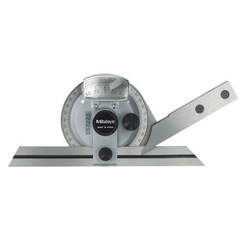
It is the simplest angle measuring instrument. A simple vernier bevel protractor with its various elements is shown in fig.2.27. The body of the bevel protractor is designed in such a way that its back is flat and there are no projections beyond its back. The base plate is attached to the main body and an adjustable blade is attached to a circular plate containing vernier scale. The main body carries a main scale graduated in degrees. The adjustable blade which is capable of rotating freely about the centre of the main scale engraved on the body of the instrument can be locked in any position. An acute angle attachment is provided at the top. The base of the base plate is made flat so that it could be laid flat upon the work piece. The blade can be moved along throughout its length and can also be reversed. The acute angle attachment can be readily fit into the body and clamped in any position. Universal Bevel protractor: The protractor dial is slotted to hold a blade which can be rotated with the dial to the required angle. It can also be adjusted independently to any desired length. The blade can be locked in any position. This instrument is capable of readings precisely within 5 minutes. Optical Bevel protractor: This instrument is capable of taking readings within 2 minutes of an arc. The interval circular scale is graduated in divisions of 10 minutes of arc. Readings are taken with the help of optical magnifying system which is an integral part of the instrument. Uses of Bevel protractor: The bevel protractors can be used to test the flatness, squareness, parallelism, straightness, angular measurements, etc. Types of…
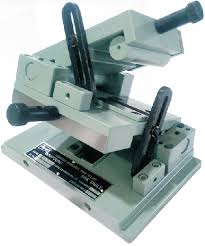
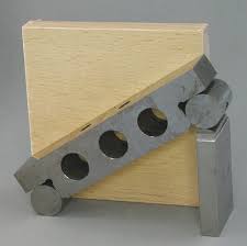
It is the most convenient and accurate design for heavy work piece. The equipment consists of a self contained sine bar hinged at one roller and mounted on its datum surface. The table is quite rigid one and the weight of unit and work piece is given fuller and safer support. The sine bar may be safely swung to any angle from 0 to 90 by pivoting it about its hinged end.
It is a precision measuring instrument and is an excellent example of combination of linear measurement and angular measurement when used in conjunction with gauge blocks (slipgauges). It consists of a bar carrying a suitable pair of rollers set a known centre distance. It is made of high carbon, high chromium corrosion resistant steel, suitably hardened, precision ground and stabilised. Relief holes are provided for easy handling of sine bar and for reducing the weight of the sine bar. It should be used on a grade A surface plate. Dial Gauge Workpiece l h Slip Gauges h Surface Plate Fig. 2.24 Sine bar If l is the linear distance between the axes of the rollers and h is the height of the slip gauges, then sin = h/l…
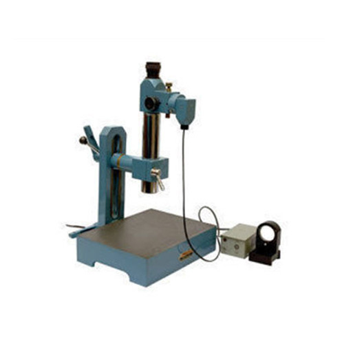
In this system, an illuminated scale is set in the focal plane of the collimating lens outside the field of view of a microscope eyepiece. It is then projected as a parallel beam and st rikes a plane reflector below the instrument. It is reflected, and refocused by the lens so that its image is in the field of view of the eyepiece. The image falls, not across a simple datum line, but across a similar fixed scale at right angles to the illuminated image. Thus, the reading on the illuminated scale measures angular deviations from one axis at 90 to the optical axis, and the reading on the fixed scale gives the deviation about an axis mutually at right angles to the other two. This feature enables angular errors in two planes to be dealt with or more important, to ensure that the reading on a setting master and on the work is the same in one plane, the error being read in the other. Thus, induced compound angle errors are avoided. The setup consists of a lapped flat and reflective base above which the optical details are mounted in a tube on an adjustable bracket. In use, a master, either a sine bar or a group of combination angle gauges is set up on the base plate and the instrument is adjusted until a reading on both sides is obtained. It is now replaced by the work, a gauge block to give a good reflective surface being placed on the face to be checked. The gauge block can usefully be held in place with elastic bands. The work is now slowly rotated until the illuminated scale moves across the fixed scale, and is adjusted until the fixed scale reading is the same as on the setting gauge. The error in the work angle is the difference in the two readings on the illuminated scale.
It is an optical instrument used for the measurement of small angular differences. It is essentially an infinity telescope and a collimator combined into one instrument. Principle of Autocollimator: If a point source of light O is placed at the principal focus of a collimating lens, it will be projected as a parallel beam of light. If this parallel beam now strikes a plane reflector which is normal to the optical axis, it will be reflected back along its own path and refocused at the source O. If the plane reflector is now tilted through some small angle „‟, the reflected parallel beam will turn through 2, and will be brought to a focus at O1, in the focal plane, a distance x from O. . If the ray passing through the geometric centre of the lens is considered, as it is, unaffected by refraction, it can be seen that x = 2 f mm, where f is the focal length of the lens. The important points about this…
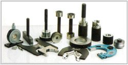
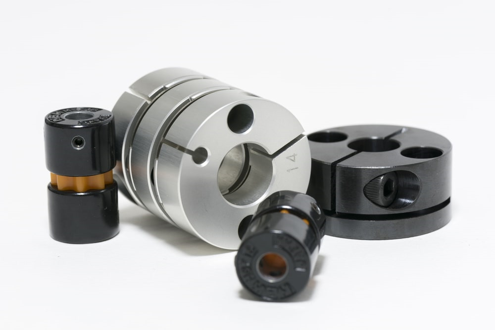
1) Full form cylindrical ring gauge: The gauging surface is in the form of an internal cylinder and whose wall is thick enough to avoid deformation under normal conditions of use. 2) Gap gauge: It has one flat surface and one cylindrical surface, the axis of the two surfaces being parallel to the axis of the shaft being checked. The surfaces constituting the working size may both be flat or both cylindrical also. The gauges (for internal taper) are marked with a ring on the gauge planes another ring to indicate the minimum depth of internal taper. The distance between the two ring marks „Z‟ corresponds to the permissible deviation of the gauge plane for particular taper. For testing the external taper of the tanged end shank, the ring gauge is inserted, as far as it goes with light pressure. At the extreme position, no part of the tang under test should extend beyond the surfaces A, B and C. The shank surfaces may however, lie flush with these surfaces.
The various types of limit gauges used for gauging internal diameters of holes are: 1) Full form cylindrical plug gauge: The gauging surface is in the form of an external cylinder. Generally a small circumferential groove is cut near the leading end of the gauge and the remaining short cylindrical surface is slightly reduced in order to act as a pilot. 2) Full form spherical plug or…
Every gauge is a copy of the part which mates with the part for which the gauge is designed. For example, a bush is made which is to mate with a shaft; in this case, the shaft is the mating part. The bush is check by a plug gauge which in so far as the form of its surface and its size is concerned, is a copy of the mating part (shaft). Taylor‟s principle: According to Taylor, „Go‟ and „No Go‟ gauges should be designed to check maximum and minimum material limits which are checked as below: „Go‟ limit: This is applied to upper limit of a shaft and lower limit of a hole. „No Go‟ limit: This is applied to lower limit of a shaft and the upper limit of a hole. Taylor‟s principle states that the „Go‟ gauges should check all the possible elements of dimensions at a time (roundness, size, location, etc.) and the „No Go‟ gauge should check only one element of the dimension at a time. Based on Taylor‟s principle, „Go‟ gauge is designed for maximum material condition and „No Go‟ gauge is designed for minimum material condition.