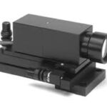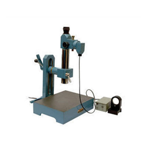
In this system, an illuminated scale is set in the focal plane of the collimating lens outside the field of view of a microscope eyepiece. It is then projected as a parallel beam and st rikes a plane reflector below the instrument. It is reflected, and refocused by the lens so that its image is in the field of view of the eyepiece. The image falls, not across a simple datum line, but across a similar fixed scale at right angles to the illuminated image. Thus, the reading on the illuminated scale measures angular deviations from one axis at 90 to the optical axis, and the reading on the fixed scale gives the deviation about an axis mutually at right angles to the other two. This feature enables angular errors in two planes to be dealt with or more important, to ensure that the reading on a setting master and on the work is the same in one plane, the error being read in the other. Thus, induced compound angle errors are avoided. The setup consists of a lapped flat and reflective base above which the optical details are mounted in a tube on an adjustable bracket.
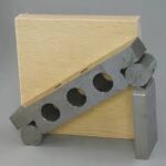
In use, a master, either a sine bar or a group of combination angle gauges is set up on the base plate and the instrument is adjusted until a reading on both sides is obtained. It is now replaced by the work, a gauge block to give a good reflective surface being placed on the face to be checked. The gauge block can usefully be held in place with elastic bands. The work is now slowly rotated until the illuminated scale moves across the fixed scale, and is adjusted until the fixed scale reading is the same as on the setting gauge. The error in the work angle is the difference in the two readings on the illuminated scale.