Graphene is the name given to a two-dimensional sheet of sp2-hybridized carbon. Its extended honeycomb network is the basic building block of other important allotropes; it can be stacked to form 3D graphite, rolled to form 1D nanotubes, and wrapped to form 0D fullerenes. Graphene is the name given to a two-dimensional sheet of sp2-hybridized carbon [1]. Graphene is a wonder material with many superlatives to its name. It is the thinnest known material in the universe and the strongest ever measured. Its charge carriers’ exhibit giant intrinsic mobility, have zero effective mass, and can travel for micrometers without scattering at room temperature [2]. Synthesis and characterization of graphenes pose challenges, but there has been considerable progress in the last year or so [3]. A great deal of research has been conducted to explore the promising properties of the single-layered graphene sheets (SLGSs) after the appearance of the new method of graphene sheet preparation. Stankovich et al. have proposed their findings related to the synthesis and exfoliation of isocyanate-treated graphene oxide nanoplatelets [4]. Implementing the chemical reduction, they have also been able to produce the graphene-based nanosheets [5]. In addition, Ferrari has reported the Raman spectroscopy of the SLGS [6].
Furthermore, Katsnelson and Novoselov have explored the unique electronic properties of the SLGSs [7]. They have stated that the graphene sheet is an unexpected bridge between condensed matter physics and quantum electrodynamics. On the other hand, Bunch et al. have reported the experimental results of using electromechanical resonators made from suspended single- and multi-layered graphene sheets [8]. The superior mechanical, chemical, and electronic properties of nanostructures make them favorable for nano engineering applications [9]. Graphene sheets are one of the most important nano-sized structural elements which are commonly used as components in micro-electro-mechanical systems (MEMS) and nano-electro-mechanical systems (NEMS) [8, 10]. Furthermore, it has been revealed that adding graphene sheets to polymer matrix could greatly improve the mechanical properties of the host polymer [11]. In addition, nanostructures such as armchair carbon nanotubes and nanoplates have shown significant potential applications in the field of environmental technologies [12]. Nano-mechanical resonators are one of most important NEMS devices which have received increasing attention from the scientific community in recent years [13-16]. The nano mechanical resonators may operate at very high frequencies up to gigahertz range [17]. The potential applications of the SLGSs as mass sensors and atomistic dust detectors have further been investigated [10]. Also, the promising usage of the SLGS as strain sensor has been examined [18].
Since graphene has a prominent application in human’s life, the necessity of mechanic analytical approach for graphene is drastically felt. There are many approaches to analyze a graphene and other nonoplates mechanically, however, they can be divided into two bunches: first, the methods that consider graphene or other nonoplates downright, and second, the methods that consider interactions between graphene and other nonoplates with their surrounding environment.The first cluster of approaches is often the Molecular Dynamics (MD) method. It is very powerful method has furthered scientists in their case studies. Sheehan et al. utilized the molecular dynamics methodology for analyzing the effect of solvents on reaction kinetics and post reaction separation is presented [19]. Kresse et al. used ab initio molecular dynamics to predict the wave functions for new ionic positions using sub-space alignment [20].With the ability to examine atomic-scale dynamics in great detail, researchers have used MD to gain new insight into problems that have been resistant to theoretical solution, such as solid fracture [21], surface friction [22], and plasticity [23]. For example, a 10-nm cubic domain of a metal can be simulated only for times less than around 10-10 s, even on very large parallel machines [22]. Increases in this simulation time require a proportional reduction in the number of atoms simulated. The results of such a simulation therefore can rarely be compared directly to experiments, since laboratory observations of these sorts of mechanical phenomena are usually made on much larger length and time scales.
One possible approach that can be applied to many problems is to use MD only in localized regions in which the atomic-scale dynamics are important and a continuum simulation method (such as finite elements) everywhere else. This general approach has been taken by several different groups of researchers. Abraham et al. [24, 25] have developed a coupled finite element, MD, tight-binding (FE/MD/TB) method in which the three methods are used concurrently in different regions of the computational domain. Another method developed recently is the quasi continuum method [26-31], in which atomic degrees of freedom are selectively removed from the problem by interpolating from a subset of representative atoms, similar to finite element interpolation in which atomic degrees of freedom are selectively removed from the problem by interpolating from a subset of representative atoms, similar to finite element interpolation. Finally Wagner et al. [32] submitted a professional coupling of atomistic and continuum simulation method that is called bridging-scale method. In this review, we are going to represent some properties of graphene and study briefly the mechanic analytical approaches that we mentioned before.
Structure, synthesis, and properties
Graphene has a honeycomb network that could have ripple in the surface. Ripples can induce the local electrical and optical properties of graphene. Three different types of graphenes can be defined: single-layer graphene (SG), bilayer graphene (BG), and few-layer graphene (FG, number of layers).Typically, the important properties of graphene are a quantum Hall effect at room temperature, an ambipolar electric field effect along with ballistic conduction of charge carriers, tunable band gap, and high elasticity. Although graphene is expected to be perfectly flat, ripples occur because of thermal fluctuations. Ideally, graphene is a single-layer material, but graphene samples with two or more layers are being investigated with equal interest.
There are now four primary ways to produce ‘pristine’ graphene:
a. Epitaxial graphene: This method involves chemical vapor deposition (CVD growth) on epitaxially matched metal surfaces
b. Micromechanical Exfoliation or micromechanical cleavage: in which highly oriented pyrolitic graphite (HOPG) is pealed using Scotch-tape and deposited on to a silicon substrate.
c. Exfoliation of graphite in solvents: Gram quantities of single-layer graphene have been prepared by employing a solvothermal procedure and subsequent by sonication. In this process, the solvothermal product of sodium and ethanol is subjected to low-temperature flash pyrolysis yielding a fused array of graphene sheets, which are dispersed by mild sonication. A single-layer graphene can be produced in good yields by the solution-phase exfoliation of graphite in an organic solvent, such as N-methylpyrrolidone (NMP). This process works because the energy required to exfoliate graphene is balanced by the solvent–graphene interaction.
“Other methods,”: such as
· Substrate-free gas-phase synthesis of graphene platelets in a microwave plasma reactor
· Arc discharge synthesis of multi-layered graphene
· Graphene can be grown on metal surfaces by surface segregation of carbon or by decomposition of hydrocarbons.
· etc.
MECHANICAL PROPERTIES
Pristine graphene structures are found in 2D plane sheets. It has a hexagonal crystal lattice which resulted in covalent bonds between carbon atoms. In the environment, graphene are discovered in tow forms: “monolayer” and “free- standing.” With the first form, we find graphene parts as a cover over a substrate material such as SiC. However, we are able to find graphene individually and independent from other materials in the environment which corresponds with the second form, “free-standing graphene” [33]. Mechanical properties for any crystal material are affected by pristine Lattice and defects are comprised of dislocations and grain boundaries [34, 35]. For example, we can mention elastic properties of materials that are affected by atoms interactions and lattice geometry, whereas strength and plastic flow stress as another properties of materials are affected by characteristics of defects. Indeed caused defects in the material severely decrease strength of it in comparison of ideal material. Anyway, we are always not able to impede the existence of defect and its effect in the materials. However, there is one exception; nano-materials can be discovered defect-free initially, and this is the main reason of superiority of strength for these materials [36]. Graphene as a nano-material is not excepted in this issue.
Lee and his co-workers performed the pioneer empirical analysis of elastic properties and strength of pristine graphene [37]. A deposited graphene membrane onto a substrate material that possesses some cavities on the surface is loaded by the tip of the atomic force microscope (Fig. 1) [37], and it was discovered that graphene brings out both nonlinear elastic behavior and brittle fracture. Thus, for nonlinear elastic behavior, we can write: σ=Eε+Dε2 σ=Eε+Dε2, where σ is the applied stress (the symmetric second Piola Kirchhoff stress), E is the Young modulus, ε is the elastic strain (uniaxial Lagrangian strain), and D is the third-order elastic stiffness. This experiment is convoyed by this result as follows: Young modulus of E = 1.0 TPa, and the third-order elastic stiffness of D = -2.0 TPa. The Young modulus they found is very close to the Young modulus of nanotubes. They also found that brittle fracture happens at an intrinsic stress as much as σint=130GPAσint=130GPA, which is very huge and magnitude.
Simulating by computer [38] shows E = 1.05 TPa and σint=110 GPaσint=110 GPa for Young modulus and brittle fracture of graphene, which is compatible with explorations of Lee and his co-workers. All of these explorations prove that graphene can be very useful for structural applications and for the cases that we are dependent on high strength. Furthermore, graphene is flexible and can be bent easily, which make it more desirable and attractive. The propagation of crack in monolayer graphene has been studied empirically and also analytically (molecular dynamics) by considering Crystallographic characteristics [39]. It has been evident that the sources of cracks in monolayer graphene membranes are unavoidable, mechanically applied stresses that are exerted during their processing. Cracks or tears propagate along the sides of the hexagonal crystal lattice and defray an occasional direction change as much as 30o in vertices of hexagonal.

It is sometimes seen that propagation can go under the TEM electron beam [40]. Kim et al. [39] used this assumption that the propagation of crack is motivated by incorporating the effects of stress concentrations at the tip of the crack and the ionization influence of electron beam. Under the simultaneous effect of these problems, atomic bonds break in the vicinities of a crack tip, and propagation takes place.
Novoselov et al. [40] performed a computer simulation on the exfoliation of graphene sheets from adhesive substrate to examine crystallographic features of cracks which happens. The idea of this simulation developed from this fact that graphene ribbons became tapered as they were produced by exfoliation process (Fig. 2). They found that tear angle is affected by adhesive strength. Their simulation showed that, with the low strength adhesive, tearing takes place in the conqueror armchair direction of the hexagonal crystal lattice of graphene, and meanwhile, occasional change in direction is observed rarely. They also concluded that any increase in adhesive strength results in more tear angel; hence, in pretty high adhesive strength a change of 60o in the direction of tearing will present.
As a material, graphene is not excluded from defects. The defects that graphene may obsess are: vacancies [41], Stone Wales defects [41], dislocations [42], and grand boundaries of GBs. Among these defects, dislocations and GBs are very common and play a prominent role in mechanical properties of graphene. For instance, dislocations can cause plastic flow in graphene, whereas GBs decrease its strength characteristics [44, 45]. Dislocations can also violate translational symmetry of graphene [46]. There is no getting around GBs in graphene specimens when it is produced in a large area; thus, their effects on mechanical properties have been always noticeable from both fundamental and applied sides. Empirical data [44] have proved that free-standing polycrystalline graphene under concentrated load has severe low failure strength when found in polycrystalline state than when produced as a single crystal. In this experiment, they used a tip of atomic force microscopy (AFM) to exert a concentrated load on a polycrystalline graphene membrane, and it was observed that the force needed to cause a tear in the graphene along GBs is an amount of 100 nN [44], this is while the force for tearing a single-crystal exfoliated graphene is not more than 1.7 mN [37]. Vargas et al. [45] did similar test using atomic force microscopy and molecular dynamics simulations to study the mechanical characteristics of a graphene with polycrystalline structure that is obtained by chemical vapor deposition. They used nanoindentation measurements and found that out-of-plane ripples effectively decrease in-plane stiffness in the mentioned graphene. They also found that GBs effectively decrease the breaking strength of the graphene. Molecular dynamics showed them voids can significantly weaken the graphene membranes. In fact, GB is a place where amorphous carbon and iron oxide nanoparticles are absorbed [45].

THERMAL PROPERTIES
The heat flow direction in a two dimensional graphene can be divided into in-plane and out-of-plane directions. In-plane heat flow is greater than out-of-plane one and is developed due to covalent sp2bonding between carbon atoms, while the latter is emanated from weak van der Waals coupling. Graphene transistors and interconnectors are beneficiaries of in-plane heat flow depending on a certain channel length. Although thermal coupling with substrate materials is miserly, it is a prominent reason for the dissipation of heat flow. We can regulate the heat flow by phonon scattering, edges, or interfaces. Ultimately, the unusual thermal properties of graphene stem from its 2D nature, forming a rich playground for new discoveries of heat-flow physics and potentially leading to novel thermal management applications.
By reviewing thermal properties, with no respect to material, one that should be considered is the specific heat. This is a quantity that implies two things: first, the thermal energy that a body is capable to store, and second, the rate of cooling and heating that a body will experiment. The later can be modeled by the thermal time constant τ ≈ RCV, where τ is the thermal time constant, R is the thermal resistance for heat dissipation (the inverse of conductance, R=1/G) and V is the volume of the body. Thermal time constants can be varied from 0.1 ns for a single graphene sheet or carbon nanotube (CNT) and 10 ns for nanoscale transistors to 1 ps for the relaxation of individual phonon modes [47 -49].
The specific heat of graphene is divided into phonons (lattice vibrations) and free electrons contributions, C=Cp+Ce, Knowing that phonon contributions are dominant [50 -52]. Phonon specific heat as a dominant coefficient becomes constant at very high temperature near in-plane Debye temperature ΘD ≈2100 K, At this time, we have Cp=3NAkB ≈25 J mol –1K–1 ≈ 2.1 J g–1K–1, also known as the Dulong–Petit limit, where NA is the Avogadro’ number and kB is the Boltzmann constant. This property belongs in a classical solid behavior when six atomic degrees of motion are entirely exited and each carries 1/2 kBT energy. In heat transport exploration, it is assumed that the thickness of a graphene monolayer is about the graphite interlayer spacing h≈3.35 A∘′h≈3.35 A°’. Graphene has one of the highest in-plane thermal conductivities at room temperature, about 2000–4000 W m–1 K–1, when it was found in freely suspended samples [53, 54]. This range corresponds with values between isotopically purified samples (0.01% C instead of 1.1% natural abundance) as a right end with large grains [55] and isotopically mixed samples or those with smaller grain sizes as a left end. Disorders with no respect of their source introduce more phonon scattering, and this results in a descendant of conductivity lower than the mentioned range [56]. Figure a compares the thermal conductivity of natural diamond (about 2200 W m–1 K–1) with those of other related materials at room temperature [57, 58]. Figure 3b exhibits the thermal conductivity of materials in Figure 3a with respect to lack of disorders.
Heat flow is strongly limited by weak van der Waals interaction in both of directions: cross-plane (along the c axis) and perpendicular to a graphene sheet, knowing that the van der Waals interaction in the perpendicular direction is between graphene and adjacent substrates, such as Sio2. As we can see in Figure 3a, the thermal conductivity along the c axis of pyrolytic graphite is just ~6 W m-1 K-1 at room temperature. The relevant metric for heat flow across such interfaces is the thermal conductance per unit area, G″ = Q″ / Δ T ≈ 50 MW m –2 K –1 at room temperature [60 -62]. This is approximately equivalent to the thermal resistance of an ∼ 25-nm layer of SiO2 [59] and could become a limiting dissipation bottleneck in highly scaled graphene devices and interconnects [63], as discussed in a later section. When we have a few layers of graphene (from 1 to 10 layers), it can be expertized that interlayer resistance, 1/ G″, remains almost constant and pretty smaller than the resistance between graphene and its nongraphene environment [61]. Indeed, the interlayer thermal conductance of bulk graphite is ∼ 24 GW m –2 K –1 if the typical 3.35- A∘A° spacing and the c axis thermal conductivity are assumed. It must be remarked that surface effects are able to decrease the thermal conductivity of graphene because of the sensitivity of phonon propagation to surface or edge perturbation, and as a result of this, the in-plane thermal conductivity of freely suspended graphene is drastically lower than a graphene nanoribbon or a graphene contacted with a substrate.

It has been seen that the in-plane thermal conductance G of graphene can reach a significant fraction of the theoretical ballistic limit in sub-micrometer samples, owing to the large phonon mean free path (λ ≈ 100 to 600 nm in supported and suspended samples, respectively). However, thermal properties of graphene could be highly tunable, so that makes it useful for heat- sinking applications when we regulate it in ultra-high thermal conductivity, and it is useful for thermoelectric applications when it is regulated for ultra-low thermal conductivity. ELECTRICAL PROPERTIES OF GRAPHENE
The electronic properties of graphene are one of the prominent cases that relating experimental researches have dealt with. The controllable continuous transformation of charge carriers from holes to electrons was one of the most notable features in pioneering researches.An example of the gate (or gate electrode is a region at the top of the transistor whose electrical state determines whether the transistor is on or off) dependence in single-layer graphene is shown in Fig. 4a. This dependency is much weaker in multiple layers of graphene because electric field is screened by the other layers. The high electronic mobility of graphene permits the development of quantum hall effect (an effect that is visible in conductor and semiconductors materials; when there are both electrical and magnetic field at the same time in a conductor or semiconductor material, it can arise an electric potential perpendicular to the magnetic field that causes electric current perpendicular to the magnetic field) at low temperatures and high magnetic fields, for both electrons and holes (Fig. 4b) (Novoselov, et al., 2005; Zhang, et al., 2005). As seen in Fig. 4b, at room temperature, the Hall conductivity σxy reveals clear plateaus at 2e2/h for both electrons and holes, while the longitudinal conductivity ρxx approaches zero. (Quantum Hall effect is measured by σ=υe2hσ=υe2h, where “e” is the elementary charge, h is the Planck’ constant, and υ is the “filling factor.” If υ is an integer, it will be an “integer quantum hall effect,” and if υ is a fraction, it will be a “fractional quantum Hall effect.” Here, at room temperature, the filling factor of graphene is υ=2.)

For sensing or transistor application, we should utilize the strong gate dependence of graphene. To do this, we should cut graphene into narrow ribbons because graphene does not have a band gap, and thus resistivity variation is small. However, graphene in narrow ribbons, makes an opening in the band gap that is proportional to the width of the ribbon by increasing the momentum of charge carriers in the traverse direction when shrinking them. This band gap in carbon nanotubes is proportional to its diameter. The opening of a band gap in graphene ribbons has recently been observed in wide ribbon devices lithographically patterned from large graphene flakes (Han, et al., 2007) and in narrow chemically synthesized graphene ribbons (Li, et al., 2008).
Molecular Dynamics (MD) modeling
Molecular dynamics is nothing but classical dynamics. Indeed classical dynamic equations of motion are valid for slow and heavy particles, with typical velocities υ<<c, (where c is the speed of light) and masses m>>me, (where me is the electron mass). Therefore, we can use them for atoms, ions, and molecular mass only in slow motion (slower than thermal vibration). This technique is based on computing potential energy that is typically considered only as a function of the system spatial configuration and is described by means of interatomic potentials. These potentials are considered as known input information; they are either found experimentally or are computed by averaging over the motion of the valence electrons in the ion’s Coulomb field by means of quantum ab initio methods. The main equation that we utilize in this technique is the Lagrange equations of motion. For a system of N interacting monoatomic molecules, the Lagrange equation turns Newtonian equations divided into “Dissipative equations” and “Generalized Langevin equations.” Integrals of motion are more functions that are useful for modeling in MD technique. Their notable property is depending only on the initial conditions and staying constant in time. Some of these equations are as follows:

where E is the total energy, P is the total momentum, and M is the total angular momentum in a system with only conservative forces.
Lattice Mechanics
Lattice mechanics is an approach to utilize natural symmetries for classical particle mechanics in materials that repetitive or regular atomic structure such as polymers or crystalline materials. This approach is based on two principles:
Principle 1: Mathematical models such as functions, matrices, operators, and so on are invariant with respect to the symmetry of lattice.
Principle 2: symmetry assumption causes loading is symmetry, and thus we will have symmetry effect.
In this approach, we use the concept of “Unit Cell” instead of particles itself. Unit Cell is an arbitrary part of a lattice, in which we could gain the whole lattice by repeating that in a fixed direction and certain distance. Hence, we can define displacement vector in a lattice in terms of unit cell as follows:

where n is the primary position of the unit cell:
rn(t)rn(t), is the position of the unit cell at time t, which is composed of the position of all particles in the unit cell at time t; un(t)un(t), is the displacement vector for the unit cell. By calculating the total lattice kinetic energy, we are able to get lattice Lagrangian and consequently the equation of motion as follows:

where U is the total Lattice Potential energy and fextnfnext is the external load on the Unit Cell n. We absolutely insist that this equation is for each unit cell, that is, with changing n we will have a system of motion differential equations.
Using Taylor series for U results in the following:

and n’n’ is indices for neighboring cell. Since we need neighboring cell in forming equations, we must define another concept as “associate cell”. Associate cell is the smallest part of a lattice that represents its mechanical properties perfectly. In lattice mechanic we restrict our studies to associate cell which can comprise several unit cells; this is the consequence of principle I discussed above.
To solve the above-mentioned equation of motion, we should use mathematics like the Fourier transform or the Laplace transform.
In terms of fextfext, we have three types of problems:
a. fext=0fext=0 or free lattice: the solution is gained by superposing of normal modes called standing waves, because the lattice oscillate around its equilibrium position.
b. fext≠0fext≠0 : to solve this type of problems we use Green’s function method that requires use of Unit pulse convolution.
c. Quasi-static problem or approximation: this is a name for time-independent problems where any noticeable change of the external forcing occurs during a period of time that is much longer than the characteristic time of atomic vibrations. This leads to eliminate the first term in motion equation, so we have the following:

To solve this equation, we can use green’s functions method. One of issue problems in quasi-static approximation is multiscale boundary conditions. We discuss this in a separate clause.
Multi scale boundary condition
Each method has its own limitations to use. These limitations are only in time and size scale. The multi scale method tries by dividing the model in different areas in terms of size and time scale (coarse-fine grain) and relating them together generates an assimilated method. In other words, we may be able to solve one part of problem with atomistic modeling and the other part with continuum; the multi scale method uses both of them concurrently and then couples them together. To couple the methods, we define a region of pseudo-atoms called handshake or pad. The position of pseudo-atoms is determined by the finite element method. The handshake has a duty to absorb the fine grain excitation and transfer the effects of coarse grain surrounding boundary. If u1 is the displacement of the pseudo-atom, u0u0 is the fine grain displacement, and uaua is the coarse grain displacement, then we can say:

where Θ and Ξ are unknown operators.
Multi scale Modeling
The philosophy of arising multiple- scale methods is that, in actuality, nano- materials are always used along with large- scale materials and we are compelled to create a method for modeling them. Atomistic methods such as MD and ab initio are not perfect to model the entire configuration because these methods are limited to time and length scales; thus, they are validated only through fine- scale parts of configuration and not for the other part. There is the same situation for continuum methods because they are validated for large time and length scale, and they are not useable for fine- scale parts of these configurations. Here is the point that the role of multiple- scale methods becomes prominent. Multiple scale methods try to blend the methods that are validated on their own scales of time and length separately.
The base of all these methods is that each scale is modeled by its special method, and their output becomes boundary condition for the other; indeed, there will be exchanges between these methods to model entire of the configuration.
Whatever method we take, it must be free of two issue problems:
· The wavelengths emitted by the MD region are drastically smaller than that can be absorbed by continuum region. It means we have differential energy for these two areas. If our approach is not capable to put in any experience for this redundant energy, it leads to this result that some of the wave will reflect back into the MD domain. This means that we will have spurious heat generation in the MD region and so a mistaken simulation especially in instances of plasticity.
· Furthermore, the transition from the MD region to the continuum region was followed with extension in timescale, which affects the validity of our relations. Hence, we must take such a method that solves this issue.
MAAD
MAAD or “macroscopic, atomistic, ab initio dynamics” is a multiple- scale approach that incorporates tight binding (TB), molecular dynamics (MD), and finite elements (FE) concurrently to model a configuration of nano- and large- scale materials. In this method, the FE Mesh will be done until we approach the same size as much as atomic spacing; from here, the MD method is entered until we arrived in a physical phenomenon like a crack tip. At this point, we will use the TB approach. Thus, we will have two overlapping regions: FE/MD and MD/TB. Not only here but also in all multiple- scale methods, such overlapping areas are termed “handshake” regions. In this method, each handshake region provides a contribution to the total energy of the system. This contribution is done by linear law in each handshake region. Thus, the total energy that will be used to find equation of motion is as follows:

There are two problems in this method. First, having finite elements in the scale of atomic space prolongs the process of solving by increasing time steps. Second, that it seems unphysical that continuum relations can be evolved at the same timescales as the atomistic variables.
COARSE-GRAINED MOLECULAR DYNAMICS (CGMD)
This approach couples FE and MD methods together. In this method to derive the governing equations of motion, we use an approximation of coarse-grained energy that converges to the exact atomic energy like the following:

UintUint represents the thermal energy of those degrees of freedom of coarse grained that have not been included in FE considered nodes. Obviously, when the number of nodes approaches the number of atoms, this term vanished and the full atomistic energy is recovered.
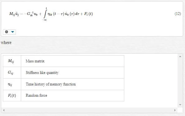
Finally the equation of motion is then given to be as follows:
QUASI-CONTINUUM METHOD
This approach is an adaptive FE method. The link between atomistic and continuum is obtained by the use of the Cauchy Born rule. The Cauchy Born rule assumes that the continuum energy density W can be computed using an atomistic potential.
The first Piola-Kirchoff stress tensor in the Cauchy Born rule is

where F is deformation gradient.
The major restriction as well as implication of the Cauchy Born rule is that the deformation of the lattice underlying a continuum point must be homogeneous. This results from the fact that the underlying atomistic system is forced to deform according to the continuum deformation gradient F.
COUPLED ATOMISTICS AND DISCRETE DISLOCATION (CADD)
This method sets a quasi-static coupling between molecular statics and discrete dislocation plasticity. One of the best assumptions in this approach is that defects within atomistic region are allowed to pass through the atomistic/continuum border into the continuum which is modeled via discrete dislocation mechanics.
Quantities such as stresses, strains, and displacements can be written in the contribution form:
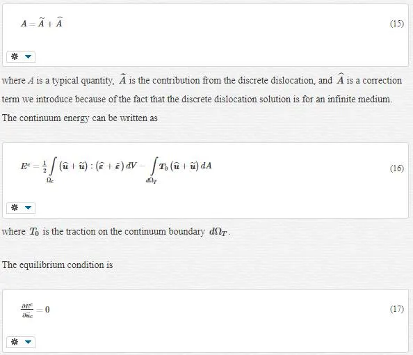
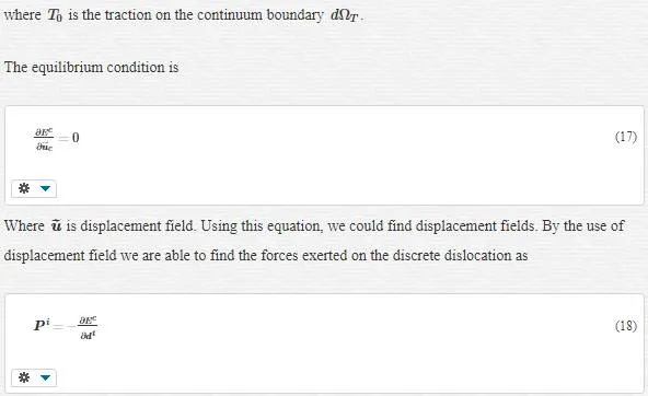
At this point, an iterative procedure involving the discrete dislocation positions, FE positions and atomic positions is solved until all degrees of freedom are at equilibrium.
However, we have some challenge in this method as follows:
· extending this approach to dynamic problems
· simulating the passage of defect from the atomistic to continuum in three dimensions
· annular dislocations that reside in both atomistic and continuum regions at the same time
BRIDGING DOMAIN
Bridging Domain is a dynamic multiple scale method that couples MD with continuum. In this method the boundary that overlays the MD region and surrounding continuum region has varying size, termed the bridging domain.
Within overlaying bridging domain, the Hamiltonian is defined as a linear combination of the molecular and continuum Hamiltonians:


Where the standard equations are augmented by the Lagrange multiplier-based constraint forces FLIFILand fLIfIL. The bar symbols overlaying the FE and MD mass matrices indicate that they need to be modified within the overlapping region.
Bridging- Scale Modeling
The bridging scale method that we want to introduce is an incorporation of MD and continuum. The total displacement as our solution is decomposed to fine and coarse- scale as follows:
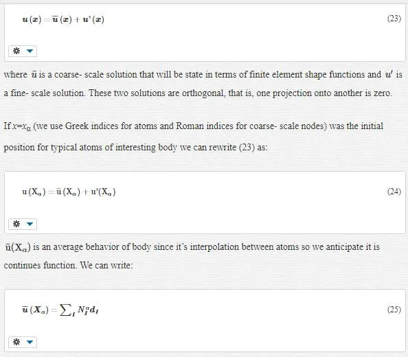
where, NαI=NI(Xα)NIα=NI(Xα) is a shape function of node I at initial atomic position Xα and dI is the displacement degree of freedom at node I.
As we said, we want to use MD method in this approach, to do this we have to utilize qα. qα is a displacement solution we derive from MD simulation (qα has the same role as u(Xα) in other words, we are simulating u(Xα) by the use of qα. Undoubtedly, qα will have projection onto u¯u¯ (coarse- scale solution) and u (fine- scale solution), and with respect to their orthogonality, each projection will not represent the other one, so we can easily find the fine- scale solution, by subtracting the projection of qαonto coarse- scale solution, from qα, that is,

where mα is the atomic mass. The choice of J (called the mass-weighted square of the fine scale) allows the coarse and fine- scale kinetic energies to be decoupled. Minimizing of J will result in WI. If we gather all masses in a matrix as follows


The last term in the above expression is called the “bridging scale”; it is that part of the molecular dynamics calculation that must be subtracted from the total in order to achieve a complete separation of scales. Our sake about the “scales” is fine and coarse scales, and our sake about “complete separation” is the orthogonality of these scales.
Indeed, P was the operator for the projection onto the coarse scale; with respect to Equation 35, we could represent another more perfect operator for this projection as

EQUATIONS OF MOTION
In this step, we will derive the coupled MD and FE equations of motions. First, we adopt the Lagrangian equation definition we submitted in MD discussion for multiscale condition as “multiscale Lagrangian.”
MULTISCALE LAGRANGIAN
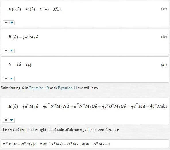

This is the desired equation for us because we have eliminated cross terms such as d and q in the kinetic energy. The bridging scale is responsible for this elimination. Using the bridging scale makes us capable of decomposing total kinetic energy into the sum of the kinetic energy in the coarse scale plus that in the fine scale.
MULTISCALE EQUATIONS OF MOTION
We can derive equations of motion by the use of Lagrangian equation:

For simplicity, we have ignored the external force. Using the chain rule, we can rewrite Equations 47 and 48 as

As we see, the derivation of potential energy U couples scales in both equations. We know that the variation of energy to displacement is the same type as force. These means we can conclude that the derivation of potential energy is the total forces on atoms:


Q is a singular since multiplying a field by Q gives the fine- scale part of the field, and many different fields can have same fine- scale part. Therefore the solution of and equation like Qu=u′Qu=u’ for u is nonunique, and Q must be singular. It is concluded that Equation 56 does not have a unique solution, and we are free to choose any q that has the proper fine- scale part and thus satisfies Equation 56. One qthat comply these conditions is that which exactly satisfies the following equation:

This is nothing but a molecular dynamics simulation for the atomic displacements, with the atomic forces given by Equation 51. So we are able to solve this equation using MD simulation.
Anyway, now we have the equation of motions as

There are some relevant comments:
· Equation 58 is a fine- scale equation of motion and a standard MD solver can be used to obtain the MD displacements q.
· Equation 59 is a coarse- scale equation of motion. This is an FE momentum equation, and to solve it, we should use finite elements method. It should be noted that for the coarse scale, the summation sign turns into integral sign.
· As we said before, q (MD solution) simulate u (real total displacement). Although we proved Equation 58 for q, it is obvious that u as real total displacement have to satisfy Equation 58 in each atomic position (Xα), this is found from Newton’s second law. u is not necessarily equal to q; they just have the same behavior like solutions of a differential equations. Indeed, initial conditions determine their equality. Thus, if these two quantities have the same initial conditions, then (which they should) then they are equal forever.
· Equality of q and u and 38 gives

It means that the coarse scale is a projection of q, and instead of solving the FE equation, we can use q. However, as we will discuss, since we will eliminate the fine scale from the coarse scale, q will be limited to fine scale (not the entire domain), and thus it is not possible to calculate the coarse- scale solution everywhere via direct the projection of the MD displacements.
· Equations 58 and 59 converge to each other if FE nodal positions approach MD atomic positions.
· This convergence makes us to conclude FE equation (Equation 59) overlays both fine and coarse scales. This is the unwanted degree of freedom that prolongs spent time for FE solution, so we should eliminate the effects of the fine scales that lie in coarse- scale region.
REMOVING FINE- SCALE DEGREE OF FREEDOM IN COARSE- SCALE REGION
In the previous section, we saw the fine- scale equation of motion (Equation 58) and coarse- scale equation of motion (Equation 59) in areas among this two- scale overlay together, and this is in contrast with the orthogonality of these two scale, so we should eliminate the effect of fine scale from coarse scale. However why do we eliminate fine scale from coarse scale and not vice versa? The answer is because eliminating one scale from the other will enter another terms in the eliminated scale’s equation of motion. Since we want to avoid wave reflection back into the MD domain and avoid heat retention within this region, we should add some terms to the fine- scale equation of motion, and it is the best opportunity for us to achieve this gold by eliminating the fine- scale effect from the coarse- scale domain. Thus, we limit our studies to the MD region and its equation of motion (Equation 58) with assumption fext=0:

To find the area that shall be removed, we should consider the behavior of these two scales. In fine scale, we have a harmonic or nonlinear potential in atomic interactions. However, at coarse scale, we have a harmonic or linear potential energy in atomic interaction. Thus, we can conclude that there is a transition area among these two scales that belong in the MD region. This is the area that shall be eliminated, and instead of this elimination, we should add some boundary conditions for the MD region. Thus, we divide the MD region in two sections: linear and nonlinear. This division is called the “linearized MD equation of motion.” Two find MD boundary condition, since we are transient from fine to coarse scale in the transition area, we use FE method and then Lattice mechanics. This means we are treating with transition area, like a coarse scale, and maybe we could say we are dividing the MD area into fine and coarse sections. We first study a chain of atoms and then consider the general state.
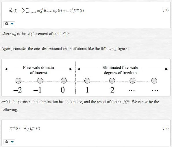
Consider a one-dimensional chain of atoms according to the following figure:
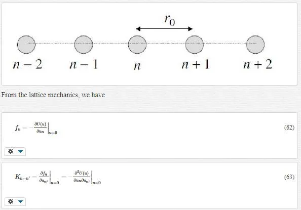
where fnfn denotes the total force on atom (unit cell) n and Kn−n’Kn−n’ is the springy factor. Using the Lagrange equation results in the equation of motion as follows

This equation is validated only for harmonic lattice, and fextn(t)fnext(t) is the total external force acting on the unit cell n.
By dividing the MD region into fine and coarse scales, we have
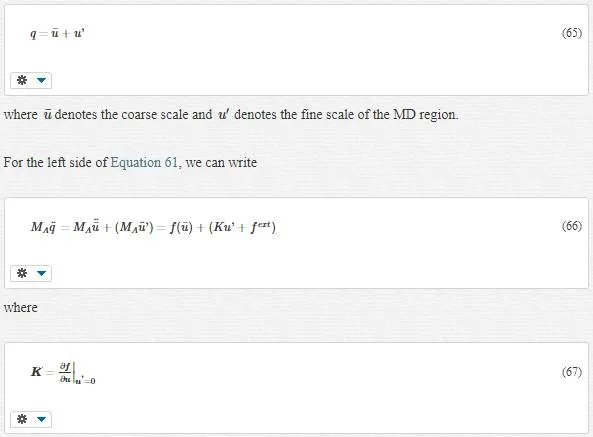
Moreover, fextfext is the total external force acting on the harmonic section of the MD by an un-harmonic section of the MD (note that fextfext is different from fextfext we neglected in Equation 48; fextfext takes place within the MD section while fextfext lies outside of this section).
A comparison between Equations 66 and 61 gives

In Equation 66, we have grouped terms based on fine scale and coarse scale. Because of the orthogonality of coarse and fine scales and that the timescale for the coarse scale is much larger than that of atomic vibrations present in the fine scale, it is reasonable to equate the corresponding parts from each side of equality sign, that is,

Equation 70 is the one we were looking for; in other words, by removing the fine- scale degree Of freedom in the coarse- scale region, Equation 61 turns into Equation 70. Thus we use Equation 70instead of Equation 61. However we still have not terminated; we should calculate fextfext as an issue problem. To do this, we use lattice mechanics.
In lattice mechanics, Equation 70 turns into Equation 71

Equation 70 is the one we were looking for; in other words, by removing the fine- scale degree Of freedom in the coarse- scale region, Equation 61 turns into Equation 70. Thus we use Equation 70instead of Equation 61. However we still have not terminated; we should calculate fextfext as an issue problem. To do this, we use lattice mechanics.
In lattice mechanics, Equation 70 turns into Equation 71:
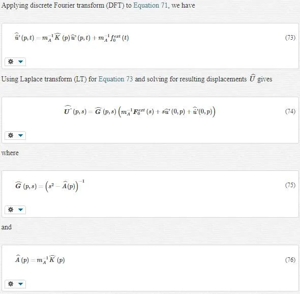
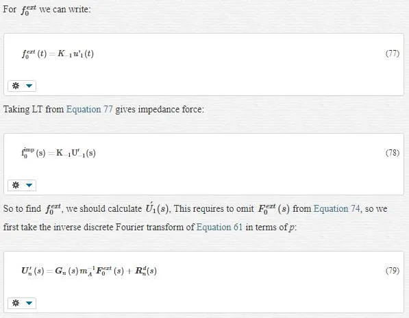
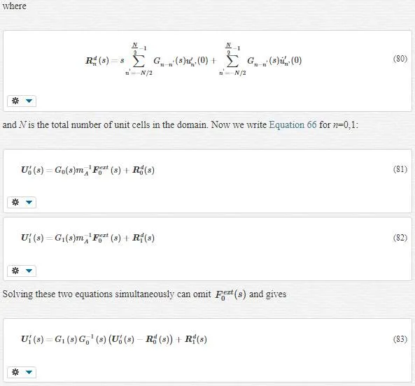
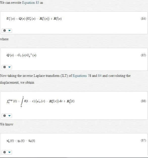
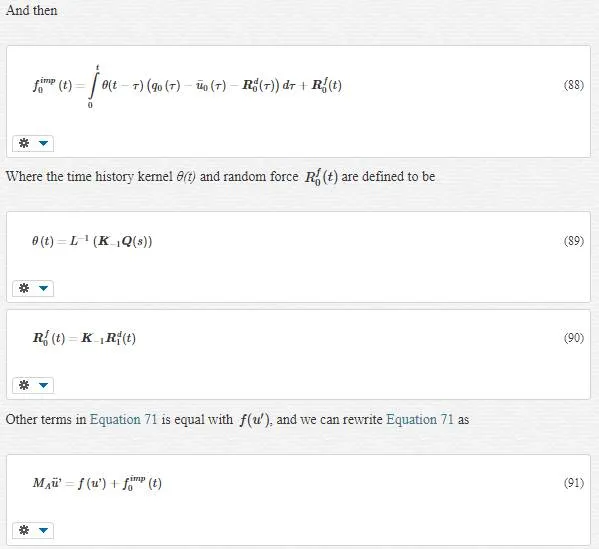
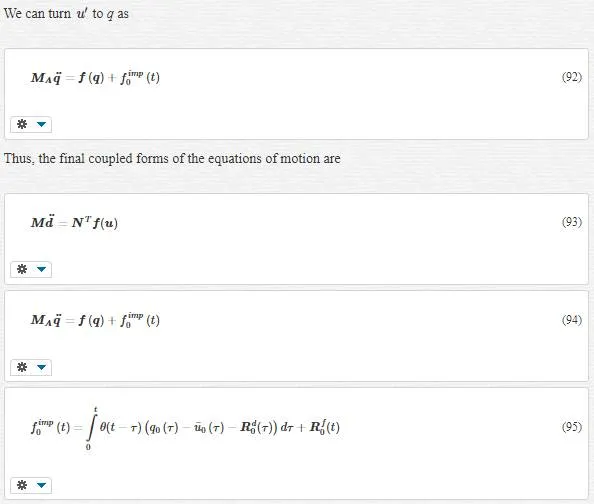
where the impedance force fimp0f0imp acts only on the boundary atom 0.
ELIMINATION OF FINE- SCALE DEGREES OF FREEDOM: 3D GENERALIZATION
In 3D state, each unit cell can be labeled with three indices, l, m, and n indicating the position along axes in the direction of the three primitive vectors of the crystal structure. The equation of motion can be rewritten as

where μ and υ represent the range of the forces in the m and n coordinate directions. We consider the one dimensional boundary condition in our study. Our boundary is located in l=0, like the following figure:
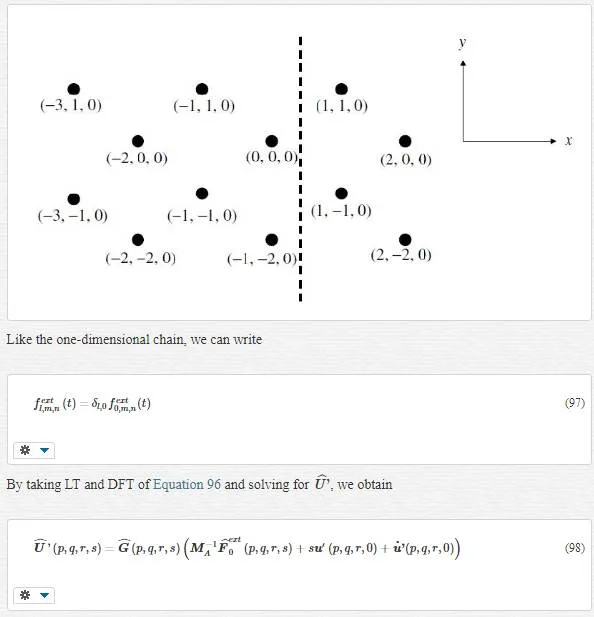

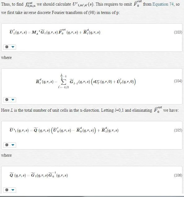
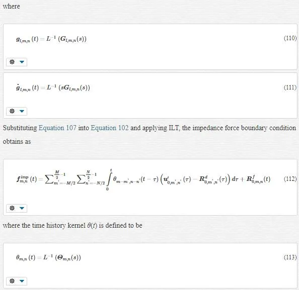
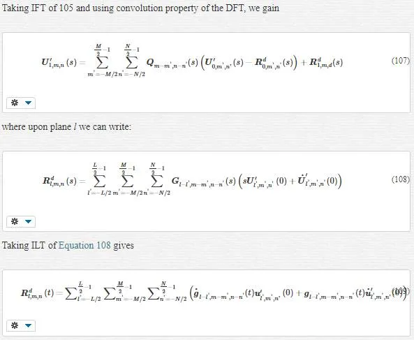
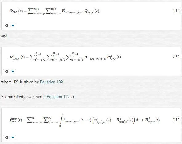
where ncnc refers to a maximum number of atomic neighbors, which will be used to compute the impedance force. Certainly, all of this ncnc atoms are located in the MD region with linear or harmonic behavior.
As we evolved in Equation 92, we can write the final coupled form of the equations of motion as:

Note:
1. The impedance force fimpfimp became an appliance for us to vanish all fine- scale information that cannot be represented in the continuum. fimp=0fimp=0 means we do not have any unharmonic area in the MD region.
2. RfRf and RdRd are called random or stochastic forces. These forces arise from the initial conditions in the eliminated fine- scale degrees of freedom. These terms represent thermally motivated displacements and forces exerted on the reduced MD system by the removed fine- scale degrees of freedom.

