
A pump starts sounding rough halfway through a production shift. A fan that once ran smoothly now makes the handrail tremble. The first instinct is often to blame “the bearings,” replace a part, and hope the vibration disappears.
That approach can be expensive and disappointing. A bearing may be healthy while a rotor is unbalanced; a new bearing can fail early if misalignment remains; and a machine can have more than one fault at the same time.
Vibration is not merely noise. It is motion with a pattern. When that pattern is measured and interpreted in context, it becomes a practical clue about force, speed, location, and developing damage.
The goal is not to diagnose every machine from one graph. It is to build a disciplined way to distinguish the usual signatures of imbalance, misalignment, and bearing faults, then confirm the likely cause before making a repair.
🧭 Start with the machine, not the spectrum
A vibration plot is useful only when its machine context is known. Record the driver and driven equipment, shaft speeds, coupling type, bearing locations, mounting arrangement, process condition, and any recent work.
A centrifugal fan, for example, may accumulate material on its impeller. A motor-pump train may shift after pipe work. A gearbox bearing has frequencies related to both shaft speed and bearing geometry. These are different physical stories, even if all three machines “vibrate.”
📏 What vibration measurements actually describe
Vibration instruments commonly report displacement, velocity, or acceleration. Displacement is often helpful for slow, large motions; velocity gives a broad indication of mechanical vibration severity; acceleration is especially useful for higher-frequency impacts such as those generated by a damaged rolling bearing.
Readings also depend on where and how the sensor is mounted. A loose handheld probe, a magnetic base, and a permanently mounted accelerometer do not respond identically at high frequencies. Trend data are most valuable when the measurement method remains consistent.
🔄 Understand running speed and “orders”
Running speed is the rotational frequency of a shaft. A shaft at 1,800 revolutions per minute turns at 30 Hz, so a vibration component at 30 Hz is called one times running speed, written 1×.
Components at 2×, 3×, and higher multiples are orders. Order thinking allows a technician to compare machines operating at different speeds. It also prevents a common mistake: treating every strong 1× peak as proof of imbalance.
🎵 Read a spectrum as a list of repeating motions
A spectrum separates a complex vibration signal into frequencies. Peaks show motions that repeat at particular rates. A time waveform, by contrast, shows how vibration changes moment by moment.
Neither view is a verdict by itself. A clean 1× peak can arise from imbalance, but also from eccentricity, a bent shaft, resonance, looseness, or hydraulic forces. Diagnosis comes from combining frequency, direction, phase, waveform, operating behavior, and inspection evidence.
⚖️ The physical cause of rotor imbalance
Imbalance occurs when a rotating assembly’s mass center does not lie on its intended axis of rotation. As it spins, that offset mass creates a centrifugal force that increases strongly with speed.
Common sources include dirt or product buildup, missing balance weights, corrosion, uneven blade repair, a damaged impeller, and manufacturing variation. Even a small mass error can become significant on a large-diameter or high-speed rotor.
📈 The classic imbalance signature
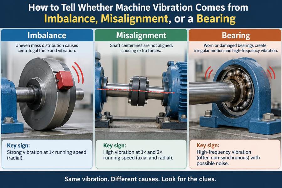
Simple imbalance commonly produces a dominant vibration component at 1× running speed. It is often strongest in the radial directions—horizontal and vertical—because the unbalance force acts outward from the rotating shaft.
On a rigidly supported machine, the spectrum may look relatively clean: one major 1× peak with smaller background components. The vibration usually rises predictably as speed rises, although resonance can make the increase far sharper near a natural frequency.
🧩 Static, couple, and dynamic imbalance
Static imbalance means excess mass is effectively concentrated in one angular location. Couple imbalance means unequal mass distribution exists in two separated planes, producing a rocking tendency. Most real rotors have some combination, called dynamic imbalance.
This distinction matters because a narrow rotor may be corrected adequately in one plane, while a wide fan rotor or long armature may require two-plane balancing. Adding a weight in the wrong plane can improve one bearing reading while worsening another.
🧱 When 1× does not mean imbalance
A dominant 1× component is a starting clue, not a final conclusion. Shaft bow, rotor eccentricity, belt or sheave runout, a rubbing rotor, soft foot, and structural resonance can all amplify motion at running speed.
Before balancing, inspect for obvious physical causes and check whether the vibration pattern changes abnormally with temperature, load, or speed. Balancing a rotor mounted on a distorted base may mask the real installation problem rather than solve it.
📐 What shaft misalignment means
Misalignment exists when the centerlines of two coupled shafts are not collinear under operating conditions. The shafts may be offset sideways, meet at an angle, or have both conditions at once.
Flexible couplings accommodate limited movement; they do not make alignment irrelevant. Their purpose is to transmit torque while tolerating specified small deviations, not to compensate indefinitely for poor installation or thermal movement.
↔️ Parallel and angular misalignment
Parallel, or offset, misalignment occurs when shaft centerlines are parallel but displaced. Angular misalignment occurs when they intersect at an angle. A real motor-pump set often has a combination.
Vertical and horizontal alignment must both be considered. A motor can be aligned accurately while cold, then move as its casing and supports heat up. This expected operating shift is called thermal growth and should be accounted for where relevant.
✖️ Typical misalignment frequency clues
Misalignment frequently produces elevated 1× and 2× running-speed vibration. In many cases, 2× is conspicuous, particularly in the axial direction near the coupling. Higher harmonics may also appear when the condition is severe or the coupling behavior is nonlinear.
These are tendencies, not universal rules. Coupling design, machine stiffness, load, speed, and nearby resonance all affect the response. A technician should compare radial and axial readings at both the driver and driven ends rather than relying on a single point.
↕️ Why axial vibration deserves attention
Imbalance often excites radial motion most strongly. Misalignment, especially angular misalignment, commonly creates useful evidence in the axial direction, along the shaft centerline.
High axial vibration does not automatically prove misalignment. Thrust loads, bent shafts, gear forces, and process forces can also excite axial motion. Still, a coupled machine with increased axial 1× and 2× near the coupling deserves an alignment investigation.
🕒 Use phase to separate look-alike faults
Phase describes where a repeating vibration occurs relative to a reference point on the rotating shaft. A tachometer or keyphasor provides that reference. Phase measurements can show whether bearings move together, oppose each other, or change sharply through a resonance.
For balance work, stable phase at 1× is particularly valuable. For alignment troubleshooting, phase relationships across the coupling can add evidence. Phase interpretation requires good measurement practice and should not be inferred from amplitude alone.
🔩 Why misalignment damages more than couplings
Misalignment creates cyclic forces that can overload coupling elements, bearings, seals, shafts, and foundations. It may increase temperature, consume energy, and shorten component life even if the machine still appears to run acceptably.
However, alignment should not be corrected blindly. First eliminate soft foot, check base condition, consider pipe strain, and verify that alignment targets reflect actual operating temperatures. Otherwise, a careful laser alignment can be undone when bolts are tightened or piping is connected.
🧲 Soft foot can imitate an alignment problem
Soft foot occurs when one or more machine feet do not sit firmly on the base. Tightening the hold-down bolts bends or twists the machine frame, changing shaft position and potentially distorting the bearing housings.
Check feet before final alignment. Correcting soft foot may require cleaning, removing burrs, improving shim practice, repairing a base, or addressing warped feet. Stacking unsuitable shims can introduce another source of instability.
🛢️ What rolling bearings are supposed to do
Rolling-element bearings support a shaft through balls or rollers that circulate between an inner race and an outer race. A thin lubricant film separates contact surfaces under normal operating conditions.
Damage can begin with contamination, inadequate or excessive lubrication, incorrect lubricant type, electrical erosion, poor fits, misalignment, overload, or simple fatigue. The visible defect is often the final stage of a longer chain of causes.
🔔 Why bearing faults create higher-frequency vibration
A crack, pit, or spall in a raceway produces a small impact whenever a rolling element passes it. Those impacts excite high-frequency structural resonance in the bearing housing and nearby machine components.
Early bearing damage may therefore be hard to see in a conventional low-frequency velocity spectrum. Acceleration measurements, high-frequency techniques, and envelope analysis can reveal repetitive impacts before overall vibration rises dramatically.
🧮 Bearing defect frequencies are calculated clues
Characteristic bearing frequencies depend on shaft speed, number of rolling elements, ball or roller diameter, pitch diameter, and contact angle. They are commonly identified as cage frequency, ball-spin frequency, outer-race pass frequency, and inner-race pass frequency.
Software can calculate these when accurate bearing data and speed are entered. Treat the result as a target region, not an exact fingerprint: slip, load zone, speed variation, and measurement resolution can shift or blur the observed components.
📡 Envelope analysis finds repetitive impacts
Envelope, or demodulation, analysis filters a high-frequency resonance band, extracts the impact envelope, and displays the repeating rate in a spectrum. It is often effective for identifying developing rolling-bearing defects.
The technique depends on selecting an appropriate filter band and obtaining a clean, well-mounted signal. A poor setup can create misleading results, while a quiet envelope spectrum does not rule out every bearing or lubrication problem.
🧯 Bearing symptoms beyond frequency peaks
Listen for changes, but do not rely on sound alone. A deteriorating bearing may show increased temperature, abnormal lubricant condition, metallic debris, roughness during slow manual rotation after safe isolation, or rising ultrasonic activity.
Each symptom has alternatives. A hot bearing may be overloaded or over-greased; noise can come from airflow or gears; metal debris may originate elsewhere. Good diagnosis asks whether several independent observations support the same explanation.
🧪 Lubrication faults can resemble bearing damage
Too little grease can increase friction and wear. Too much grease can churn, raise temperature, and force lubricant into unwanted areas. Contaminated lubricant can produce abrasive wear and repetitive impact-like activity.
Do not add grease solely because vibration rose. Follow the equipment manufacturer’s lubrication method, amount, interval, and cleanliness requirements. If condition monitoring is available, use it to decide whether relubrication is appropriate rather than treating grease as a universal remedy.
🗂️ Compare the main patterns carefully
| Likely condition | Common vibration evidence | Useful confirmation |
|---|---|---|
| Imbalance | Predominantly radial 1×; often stable phase | Inspect rotor, check runout and deposits, perform controlled balance correction |
| Misalignment | Elevated 1× and often 2×; axial vibration can be prominent | Check soft foot, pipe strain, thermal targets, and shaft alignment |
| Rolling-bearing defect | High-frequency impacts; envelope peaks near bearing frequencies and harmonics | Verify bearing data, inspect lubrication and temperature, trend the condition |
The word “common” is deliberate. Machine dynamics are coupled: one defect can excite another, and a flexible structure can reshape every apparent signature.
🧱 Check the structure before blaming the rotating parts
Loose hold-down bolts, cracked welds, degraded grout, weak baseplates, and loose bearing housings can amplify vibration. Mechanical looseness often generates multiple harmonics of running speed and may cause unstable readings.
A resonance occurs when forcing frequency approaches a natural frequency of the machine or support structure. The result can be a large response to a modest force. Correcting the force source helps, but changing stiffness, mass, or operating speed may also be required.
🌊 Process forces can change the diagnosis
Pumps may vibrate differently with flow, suction condition, recirculation, or cavitation. Fans can respond to damper position, airflow instability, and deposits. Compressors can be influenced by pulsation and valve condition.
Take measurements under documented operating conditions. If vibration rises only at a particular flow or speed, the process may be central to the problem. A mechanical repair performed without considering operation can leave the symptom unchanged.
🧰 A practical inspection sequence
- Confirm that the machine can be assessed safely and identify the shaft speeds.
- Review trend history, recent maintenance, and operating changes.
- Inspect guards, fasteners, base condition, coupling, leaks, deposits, and lubricant condition.
- Measure vibration consistently in horizontal, vertical, and axial directions at relevant bearings.
- Collect spectra and waveforms; add phase or envelope data when the suspected fault warrants it.
- Compare evidence with machine design and operating state, then choose the least invasive confirming check.
This sequence prevents the common error of jumping from a single elevated overall reading directly to a replacement part.
📍 Measure at locations that answer a question
At minimum, collect radial measurements in two perpendicular directions and an axial measurement on accessible bearing housings. On a motor-pump train, readings at both inboard and outboard positions help locate where energy is entering the structure.
Use a tachometer reference when order tracking or phase matters. Label every route point clearly. A trend becomes unreliable if “motor drive-end horizontal” quietly changes to a different spot, direction, or mounting method.
📉 Trend change is often more useful than one number
A machine may have a harmless structural characteristic that produces a repeatable spectral peak for years. Another machine may remain below a general alarm limit while a bearing-defect frequency steadily rises. Context and rate of change matter.
Establish a baseline after known-good installation or repair whenever possible. Investigate abrupt changes, persistent upward trends, new frequency families, and changes that correlate with temperature, speed, or load.
🚫 Avoid the “replace and hope” repair
Replacing a bearing without correcting alignment, contamination, electrical discharge, or improper fit may repeat the failure. Balancing an impeller without removing buildup or fixing a damaged blade can provide only temporary improvement.
Likewise, alignment is not a cure for all 2× vibration, and lubrication is not a cure for every noisy bearing. A repair should follow a documented fault hypothesis and include a post-repair measurement to verify the result.
🧑🏭 Know when to escalate the work
Stop and involve qualified personnel when vibration is rapidly increasing, a bearing housing is unusually hot, rubbing is suspected, a guard or foundation is loose, or the machine serves a safety-critical process. Follow site procedures for shutdown, lockout, and inspection.
Specialist help is also sensible when spectra conflict, the machine crosses resonance, a large rotor needs field balancing, or alignment requires thermal-growth modeling. Condition monitoring reduces uncertainty; it does not remove the need for engineering judgment.
🧠 The core diagnostic principle
Imbalance is fundamentally a rotating mass-force problem, so it often appears as stable radial 1× vibration. Misalignment is a coupled-shaft geometry problem, so axial response and 1×/2× patterns near the coupling become useful. Bearing damage is an impact problem, so high-frequency and envelope evidence become especially valuable.
Those distinctions guide investigation, but none should be used as a shortcut around inspection, operating data, and confirmation. The most reliable diagnosis is the one that explains the vibration pattern and the machine’s physical condition.
Measure the pattern, understand the machine, and confirm the cause before choosing the repair. That discipline turns vibration from a vague warning into an actionable maintenance tool. ⚙️📈🔧