
A car climbs a hill without the engine racing beyond its useful range. A conveyor starts a loaded belt smoothly. A wind turbine turns slowly while its generator operates much faster. In each case, a gearbox is doing more than simply “making things turn.”
It is changing the relationship between speed, torque, and direction while carrying substantial forces in a compact enclosure. The quiet, dependable operation people expect depends on parts that must work together with very little margin for error.
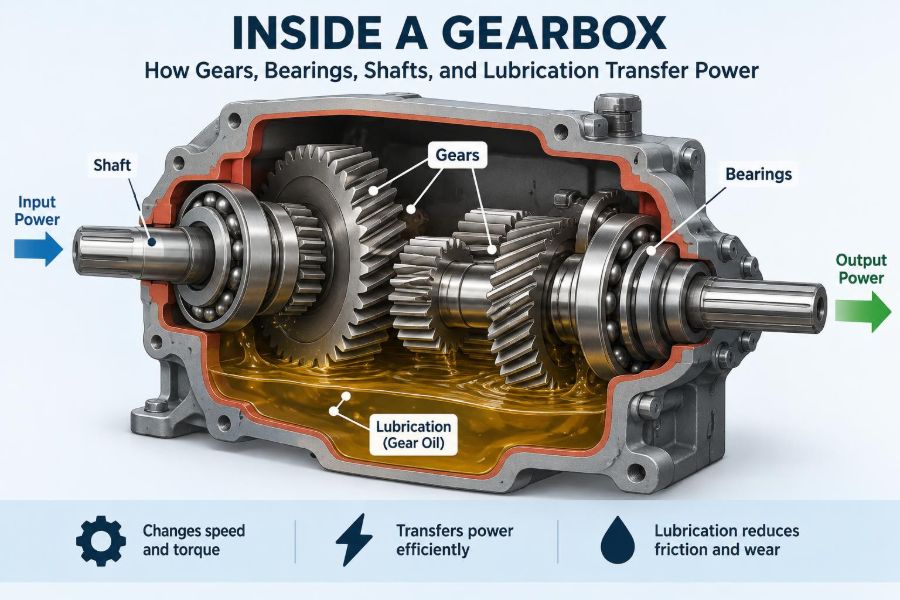
Open a gearbox housing and the arrangement can look deceptively simple: toothed wheels on shafts, bearings at the ends, and oil in the bottom. Yet each part controls a different aspect of power flow, and a weakness in one often becomes a problem for all the others.
Understanding that system helps students connect machine-design theory to real hardware and helps practitioners diagnose noise, heat, vibration, and premature wear before a minor defect becomes a shutdown.
⚙️ A Gearbox Is a Power-Management System
A gearbox transfers rotating mechanical power from an input machine to an output machine. Its central purpose is usually to trade speed for torque, although it can also reverse rotation, change shaft direction, or split power between outputs.
Power is approximately the product of torque and angular speed: P = Tω. Losses mean output power is always somewhat lower than input power, but a reduction in speed can produce a proportional increase in available output torque.
A bicycle is a familiar example. Selecting a lower gear makes the wheel turn fewer times for each pedal revolution, but makes it easier to apply wheel torque against a hill.
🔄 Following the Path of Power
Power enters through an input shaft, passes through one or more gear meshes, and leaves through an output shaft. Bearings support the shafts, while the housing holds the bearing locations in the correct geometric relationship.
Lubricant sits throughout this path: it forms films between gear teeth and rolling elements, carries heat away, and transports contaminants toward filters or magnetic plugs. Seals keep oil inside and dirt outside.
A useful mental model is a relay team. Gears exchange force and motion, shafts transmit torque between stations, bearings guide the runners, and oil keeps contact surfaces from stumbling under load.
📐 Gear Ratio Defines the Trade-Off
For a simple external gear pair, the speed ratio is determined by tooth count. If a 20-tooth pinion drives a 60-tooth gear, the larger gear rotates at one-third of the pinion speed. This is commonly called a 3:1 reduction.
Ignoring losses, torque rises by the same ratio. If the input torque is 10 N·m, the ideal output torque would be 30 N·m. Actual output is lower because friction, churning, seals, and bearing losses consume some power.
In multistage reducers, individual ratios multiply. Designers use this to achieve large reductions without requiring one impractically large driven gear.
🦷 What Happens Where Gear Teeth Meet
Gear teeth do not push continuously across their whole faces. Contact begins near one end of a tooth profile, moves across the contact path, and transfers to the next tooth pair. The profile geometry is designed to maintain a nearly constant speed ratio during that movement.
Most industrial gears use the involute profile. Its practical advantage is tolerance of small center-distance changes without losing the basic constant-ratio action. It does not make misalignment harmless; it simply gives useful geometric robustness.
At the tooth contact, forces include a tangential component that transmits torque and radial or axial components that load shafts and bearings. Gear design is therefore inseparable from bearing selection and housing stiffness.
🧩 Spur Gears: Simple Parallel-Shaft Drive
Spur gears have straight teeth parallel to the shaft axis. They are efficient, straightforward to manufacture, and common in moderate-speed parallel-shaft applications.
Their limitation is engagement behavior. An entire tooth width begins engagement nearly at once, which can create a noticeable impact and tonal noise at higher rotational speeds.
Spur gears also create radial separating force but essentially no axial thrust in an ideal arrangement. This can simplify bearing arrangements compared with helical gearing.
📏 Helical Gears: Smoother, With a Cost
Helical teeth are angled across the gear face. Engagement progresses gradually, allowing more overlap between teeth and generally smoother, quieter operation than a comparable spur pair.
The helix angle also produces axial thrust. Bearings must resist this force, and the gearbox casing must transmit it without allowing shaft positions to shift excessively.
Double-helical or herringbone gears use opposing helix directions to cancel much of the net thrust. They offer excellent smoothness, but manufacture and assembly are more involved.
🧭 Bevel and Worm Gears Change Direction
Bevel gears transmit motion between intersecting shafts, often at 90 degrees. They are used where the drive must turn a corner, such as certain differential and right-angle drive arrangements.
Worm gearsets pair a screw-like worm with a worm wheel on a perpendicular shaft. They can provide high reduction in one stage and may resist back-driving in some designs, but friction and heat are major design concerns.
Self-locking should never be assumed merely because a drive uses a worm. Whether back-driving occurs depends on lead angle, friction, lubrication, loading, and condition; safety-critical holding functions need independent braking or restraint.
🪐 Planetary Gears Pack Power Densely
A planetary set has a central sun gear, planet gears carried by a rotating carrier, and an outer ring gear. Holding or driving different members produces different ratios and directions.
Because several planets can share the load, planetary gearboxes can transmit high torque in a compact, coaxial package. They are widely used in automatic transmissions, robotics, turbine drives, and compact industrial reducers.
Load sharing is not automatic. Manufacturing accuracy, carrier stiffness, tooth modifications, and assembly quality determine whether the planets actually divide load evenly.
🔗 Shafts Carry Torque Between Components
A shaft delivers torque from one mounted component to another while also resisting bending from gear forces, pulley loads, couplings, and its own weight. It may look like a plain cylinder, but stress varies along its length.
Torque creates shear stress; transverse gear forces create bending stress. Where these combine, fatigue design becomes especially important, particularly at shoulders, keyways, splines, and changes in diameter.
Good shaft design balances strength, stiffness, manufacturability, and serviceability. A shaft that does not break can still be unacceptable if it deflects enough to misalign gears or overload bearings.
🔩 Keys, Splines, and Fits Transfer Torque
Gears must be connected to shafts without slipping. A keyed joint uses a removable rectangular key, while splines use multiple teeth around the shaft circumference and can distribute load more evenly.
Interference fits and shrink fits can transmit torque through friction. They avoid keyway stress concentrations but demand controlled assembly and can complicate maintenance.
No joint is universally best. A lightly loaded serviceable machine may suit a key, while a high-torque reversing application may justify splines or a carefully engineered shrink fit.
🎯 Why Shaft Alignment Matters
Alignment means more than making shafts appear visually straight. It includes angular alignment, parallel offset, correct center distance, and the position of gear contact across the tooth face.
Misalignment concentrates load near one tooth edge. The local contact stress rises, lubricant film becomes harder to maintain, and the same defect can impose edge loading on bearings.
Flexible couplings accommodate limited installation error and thermal movement, but they do not excuse poor alignment. Excessive misalignment still generates coupling forces and vibration.
🛞 Bearings Locate and Support the Shafts
Bearings reduce friction while controlling shaft motion. They support radial loads, axial loads, or a combination, and they establish the running position of gears relative to one another.
Rolling-element bearings use balls or rollers between rings. Plain bearings support the shaft on a pressurized or wedge-shaped oil film and can perform exceptionally well at high speeds or heavy continuous loads when properly supplied with oil.
The correct bearing is selected from load direction, magnitude, speed, required stiffness, available space, lubrication method, and expected operating life.
⚖️ Radial Loads and Axial Loads Are Different
A radial load acts perpendicular to a shaft, as with the separating force from spur gears. An axial or thrust load acts along the shaft, as with helical and bevel gears.
Deep-groove ball bearings can handle moderate combined loading. Tapered roller bearings and angular-contact ball bearings are commonly arranged to handle significant thrust while maintaining accurate shaft location.
Using a bearing that can carry the load is only part of the task. The arrangement must control motion in both directions without creating unwanted preload as the housing and shaft change temperature.
📍 Locating and Floating Bearing Arrangements
Many gearboxes use one locating bearing position and one floating position. The locating end fixes the shaft axially; the floating end permits thermal expansion so the shaft does not build excessive internal thrust.
In another arrangement, opposed angular-contact or tapered roller bearings are preloaded to eliminate clearance and improve stiffness. Preload must be set carefully: too little permits motion, while too much raises friction and heat.
This is a system decision. Gear thrust, housing expansion, shaft length, and assembly tolerance all affect the right arrangement.
🏠 The Housing Is a Structural Component
The gearbox housing is not merely a container for oil. It maintains bearing bores, resists gear-separating forces, provides mounting surfaces, damps some vibration, and helps reject heat.
A flexible housing can allow bores to move under load. That changes tooth contact and bearing loading even if the gears and bearings were specified correctly on paper.
Ribs, wall thickness, machined joint faces, and mounting-foot stiffness all influence real operating alignment. Casting quality and machining accuracy matter because a small positional error can affect every rotating part.
🛢️ Lubrication Creates a Protective Film
Lubrication is the mechanism that separates surfaces which would otherwise rub, weld locally, or wear rapidly. In a healthy gear contact, an oil film carries much of the load while allowing the surfaces to slide and roll relative to each other.
The film also reduces frictional heating, protects against corrosion, carries debris toward collection points, and quiets contact. Gear oil is therefore both a lubricant and a heat-transfer medium.
Film thickness depends on viscosity, speed, load, surface finish, and temperature. A lubricant that works at a light-load test speed may not maintain separation during a hot, heavily loaded duty cycle.
🌡️ Viscosity Must Match Temperature and Duty
Viscosity describes resistance to flow. Oil that is too thin at operating temperature may not form an adequate film; oil that is too thick can cause high churning loss, poor cold starting, and excess temperature.
Selection must consider the gearbox manufacturer’s recommendation, ambient temperature, gear type, load, speed, and lubrication system. Additive chemistry also matters, especially for heavily loaded sliding contacts such as worm gears.
Changing oil grade because “thicker is safer” can create a new problem. The right lubricant is the one that reaches contacts reliably and provides suitable film under actual operating conditions.
💦 Splash, Bath, and Forced Lubrication
In splash lubrication, a rotating gear dips into an oil sump and carries oil to meshes and bearings. It is simple and effective within designed speed and level limits.
Too high an oil level can make gears churn through oil, raising temperature and aerating the lubricant. Too low a level may starve an upper mesh or remote bearing.
Forced-circulation systems use a pump, piping, and often filters or coolers. They are useful where speed, load, or layout makes splash delivery unreliable, but introduce components that require monitoring.
🫧 Air, Water, and Dirt Degrade Oil
Foam can prevent a stable oil film and make level readings misleading. It may result from overfilling, unsuitable oil, excessive churning, or air drawn into a circulation system.
Water promotes corrosion and can weaken lubricant performance. Dust and wear particles act as abrasives, accelerating damage in gears and bearings.
Breathers, seals, desiccant devices where appropriate, filters, and clean filling practices are practical defenses. Clean oil is not a cosmetic preference; it is part of contact-survival strategy.
🔥 Where Gearbox Heat Comes From
Heat is generated at gear meshes, bearing contacts, seals, and in the oil itself as it churns. A compact enclosure can retain that heat faster than its external surface can release it.
Rising temperature lowers oil viscosity, which can reduce film thickness and further increase friction. This feedback loop explains why a lubrication or alignment problem may worsen quickly under sustained load.
Cooling fins, larger housings, circulation coolers, correct oil level, and reduced losses can all help. The appropriate solution depends on a heat balance, not simply on adding more oil.
📣 Noise and Vibration Reveal Gear Behavior
Every gear mesh produces a characteristic mesh frequency related to tooth count and rotational speed. A steady tonal sound may be normal, while a growing tone, sidebands, or broad roughness can indicate developing faults.
Common sources include backlash variation, eccentric gears, damaged teeth, bearing defects, looseness, and resonance of the housing or attached structure. Sound alone does not identify a fault with certainty, but it directs investigation.
Comparing vibration trends at similar operating conditions is often more useful than treating one isolated reading as a diagnosis.
↔️ Backlash Is Clearance, Not Sloppiness
Backlash is the intentional clearance between mating teeth measured along the pitch circle. It allows lubrication, accommodates thermal expansion and manufacturing variation, and prevents tooth interference.
Too little backlash can cause tight running and overheating as components expand. Too much can increase impact during reversing loads and may worsen positional error in precision motion systems.
The target depends on size, material, operating temperature, accuracy requirements, and duty. “Zero backlash” mechanisms still require an engineered way to avoid binding.
🧱 Tooth Damage Has Recognizable Patterns
Pitting is small surface fatigue damage caused by repeated contact stress. Scuffing is more severe adhesive damage associated with film failure, high sliding, and temperature. Broken teeth can result from overload, fatigue cracks, poor contact, or impact.
Wear patterns are diagnostic clues. Damage concentrated at one edge suggests misalignment; widespread polishing may be benign running-in or may indicate contamination, depending on severity and progression.
- Micropitting: fine gray surface distress often linked to thin-film conditions.
- Spalling: larger flakes or pieces detach after subsurface fatigue develops.
- Corrosive attack: chemical or moisture-related surface degradation.
Failure labels should lead to root-cause analysis, not just replacement. New gears installed into the same misaligned or contaminated system may fail in the same way.
🩺 Bearing Damage Also Tells a Story
Rolling bearings can develop raceway fatigue, smearing, cage damage, corrosion, false brinelling from vibration at rest, or electrical erosion in certain electrically active machinery.
Incorrect preload, poor fits, contamination, inadequate lubrication, and shaft deflection are recurring contributors. A bearing may be the visibly failed part while the underlying cause originates in a gear mesh or distorted housing.
During inspection, technicians should note damage location and orientation. Those details can reveal whether the dominant problem was thrust, misalignment, lubrication starvation, or assembly error.
🧰 Installation Practices Protect the Design
Cleanliness during assembly is essential. A small abrasive particle introduced during repair can circulate through highly loaded contacts for many operating hours.
Pressing a rolling bearing onto a shaft should apply force to the ring with the interference fit, not transmit force through the rolling elements. Heating methods, specified torque procedures, and correct tools reduce assembly damage.
Before startup, confirm lubricant type and level, free rotation where appropriate, fastener condition, coupling alignment, and breather installation. Initial operation should include checks for abnormal heat, leaks, and noise.
🔍 Condition Monitoring Finds Trends Early
Routine checks begin with simple observations: oil level, leaks, temperature change, noise, vibration, and breather condition. These observations become more valuable when recorded consistently.
Oil analysis can identify particles, water, viscosity changes, and chemical degradation. Vibration analysis can highlight periodic signatures associated with gears or bearings. Neither method replaces inspection, but each can prioritize it.
A practical monitoring program matches the consequence of failure. A lightly loaded auxiliary drive may need basic rounds, while an inaccessible or production-critical gearbox can justify more detailed trending.
🚫 Common Troubleshooting Mistakes
One common mistake is replacing a noisy bearing without checking gear contact, shaft fit, or alignment. Another is adding oil to address heat without verifying the specified level, which can increase churning losses.
It is also risky to interpret every metallic particle as catastrophic. New or recently rebuilt units may produce limited running-in debris, whereas a rising trend, large particles, or a change in operating symptoms deserves prompt evaluation.
- Do not mix lubricants unless compatibility is confirmed.
- Do not adjust backlash by guesswork without measuring contact and clearance.
- Do not operate with damaged seals simply because the oil level is still visible.
- Do not treat a repeated failure as an isolated component defect.
🏗️ Design Requires System-Level Decisions
A gearbox is designed through compromises. Higher helix angle may improve smoothness but increases thrust. A compact housing saves space but may challenge heat rejection. Tighter tolerances improve accuracy but raise manufacturing cost.
Service requirements matter as much as rated torque. Access for oil changes, drain location, inspection covers, lifting provisions, spare-parts availability, and sensor locations influence lifecycle reliability.
The most successful designs connect calculations to real duty: starts and stops, shock loads, reversing, ambient conditions, mounting flexibility, and maintenance capability.
🧠 The Core Principle: Control Contact and Motion
Gears transfer torque through controlled tooth contact. Shafts preserve the geometry and carry the resulting loads. Bearings locate the shafts with low friction, while the housing keeps every centerline stable under force.
Lubrication makes those controlled contacts survivable by separating surfaces, removing heat, and carrying contaminants away. When any one element loses control—through misalignment, inadequate film, loose fits, or distortion—the other elements inherit the consequences.
A gearbox succeeds when its components maintain the intended geometry, load path, and lubricant condition throughout real operating life, not merely when it turns freely on the assembly bench.
That systems view turns a gearbox from a collection of parts into a clear engineering lesson: power transfer is reliable only when force, motion, heat, and cleanliness are managed together. ⚙️🛢️🔧