
A pedestrian presses a button at a crosswalk. A door slides open, a train slows smoothly into a station, and a production line places a tiny component precisely where it belongs. These ordinary moments depend on machines that convert energy into controlled motion.
Behind each one is more than a clever sketch. Someone had to decide how much force was needed, where heat would go, what material could survive repeated use, how parts would be made, and what would happen when a sensor or bearing eventually failed.
That work is the practical heart of mechanical engineering: turning a useful idea into a physical system that moves, carries loads, manages energy, and performs reliably outside the drawing board.
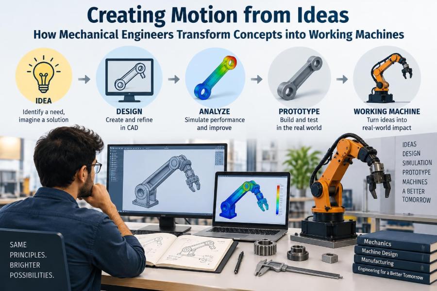
The path from concept to machine is rarely straight. It is an iterative process of defining needs, making assumptions, calculating, modeling, testing, finding weaknesses, and improving the design until its behavior is understood well enough for real use.
🧭 Mechanical Engineering Begins with a Need
Mechanical engineers do not usually begin by choosing a gear, motor, or material. They begin with a problem statement: a clear description of what must be accomplished and under what conditions.
A warehouse cart, for example, may need to carry a specified load through narrow aisles, remain stable over floor joints, be affordable to manufacture, and require little maintenance. “Make a cart” is not a useful engineering requirement; those measurable needs are.
Good requirements prevent elegant but unsuitable solutions. They also expose trade-offs early, before expensive design work begins.
🎯 Translating Wishes into Engineering Requirements
Users often describe desired outcomes in everyday language: quieter, faster, easier to use, safer, or lighter. Engineers translate those wishes into quantities that can be checked.
- “Faster” may become a target cycle time or maximum acceleration.
- “Quieter” may require limits on vibration, gear noise, or airflow noise.
- “Safer” may require guarded pinch points, predictable stopping behavior, and fault detection.
- “Long-lasting” may become a duty cycle, service interval, and design life.
Not every requirement has equal priority. Separating must-have constraints from desirable features helps teams make disciplined decisions when time, cost, and physical limits conflict.
🔍 Understanding the Operating Environment
A machine behaves differently in a clean laboratory than on a construction site, a food-processing line, or the deck of a vessel. Temperature, humidity, dust, vibration, corrosion, cleaning chemicals, and operator behavior can reshape an otherwise sound design.
Consider an outdoor actuator. Rain may enter a housing, cold may thicken lubricants, sunlight may age polymer covers, and wind can add unplanned loads. The engineer must design for the actual environment, not the ideal one.
This is why site visits, user interviews, and observation are valuable technical activities. They reveal conditions that rarely appear in a brief specification.
⚖️ Choosing What the Machine Must Optimize
Engineering is often an exercise in managing competing objectives. A thicker component can be stronger but heavier. A larger motor may accelerate a load better but increase cost, energy use, and packaging space.
There is seldom one universally best design. Instead, engineers seek the best option for a defined application. A racing bicycle, a hospital bed, and a mining conveyor all prioritize different combinations of mass, durability, serviceability, precision, and cost.
Making these trade-offs explicit is better than allowing them to emerge accidentally during manufacturing or field use.
📐 First-Pass Physics Creates a Reality Check
Before building detailed models, engineers use fundamental relationships to estimate whether an idea is plausible. Force, torque, speed, power, pressure, heat flow, and energy provide a quick reality check.
For rotating equipment, torque causes angular acceleration while power describes how quickly work is delivered. A motor may have enough torque to lift a load slowly but insufficient power to lift it at the required speed.
Simple calculations are not obsolete because simulation exists. They establish scale, reveal incorrect assumptions, and give engineers a benchmark for judging later software results.
🧱 Loads, Stresses, and the Strength of Parts
Every structural part carries some combination of tension, compression, bending, shear, or twisting. These internal effects create stress, meaning force distributed over an area, and strain, meaning deformation relative to original size.
A shelf bracket bends because the load creates a moment, or turning effect, about its attachment. A drive shaft twists because transmitted torque produces shear stress. Understanding the load path—how force travels through connected parts—is essential.
Engineers also consider how loads change. A stationary load may be modest, while repeated starts, impacts, or reversals can create much more demanding conditions.
🔄 Fatigue Changes the Meaning of “Strong Enough”
Many components do not fail because of one dramatic overload. They fail after repeated stress cycles through a process called fatigue. Small cracks can begin at holes, sharp corners, scratches, weld transitions, or other local stress concentrations.
A paper clip illustrates the principle: it can withstand a small bend, but repeated bending eventually causes fracture. Machine parts face the same issue, though the forces and materials are more complex.
Designing against fatigue may involve smoother geometry, better surface finish, larger radii, improved joints, lower operating stress, or inspection plans. The expected number of cycles matters as much as peak load.
🧪 Materials Are Selected for More Than Strength
Material choice balances mechanical properties with manufacturing, environment, cost, and maintenance. Steel offers many useful strength and toughness options; aluminum can reduce mass; polymers can resist corrosion and provide low friction; composites can offer high stiffness relative to weight.
A material’s stiffness, wear behavior, thermal expansion, corrosion resistance, and ease of joining may matter more than its headline strength. For instance, a stiff material may preserve alignment, while a softer one may damp vibration or protect a mating component.
Availability also matters. A difficult-to-source material can turn a good prototype into a difficult production program.
🌡️ Heat Is Often a Hidden Design Load
Friction in bearings, electrical losses in motors, compression in pneumatic systems, and hot process fluids all generate heat. If that heat is not transferred away at a sufficient rate, temperatures rise and change machine behavior.
Lubricants can thin or degrade, clearances can close as parts expand, electronic components can become unreliable, and polymer parts can soften. Thermal design therefore includes conduction through solids, convection to fluids, radiation where relevant, and deliberate cooling paths.
A compact machine is not automatically efficient. Packing heat-generating components tightly can make thermal management one of the central design constraints.
💧 Fluids Create Useful Force and Difficult Losses
Fluid power systems use pressurized liquids or gases to create motion. Hydraulics are often chosen where high forces are needed in compact actuators, while pneumatics can suit fast, relatively simple motions where compressed air is available.
Flow resistance causes pressure loss, and restrictions, bends, valves, and hoses all influence system response. Air is compressible, so pneumatic actuators can behave differently from hydraulic cylinders under changing loads.
Pumps, seals, filters, reservoirs, hoses, and fittings must be treated as a connected system. A powerful actuator cannot compensate for undersized lines, contamination, or a poorly controlled valve.
⚙️ Mechanisms Convert Input into Useful Motion
A mechanism is an arrangement of components that guides or transforms motion. Gears change speed and torque; belt drives connect separated shafts; linkages turn rotation into an oscillating or linear path; cams produce programmed motion profiles.
The familiar bicycle is a compact lesson in mechanisms. Pedal force creates crank torque, a chain transfers it, sprockets change the speed ratio, and wheel-ground contact converts rotation into forward travel.
Selecting a mechanism means considering efficiency, backlash, noise, packaging, maintenance, contamination tolerance, and the precision required at the output.
🧮 Kinematics Describes Motion Before Forces
Kinematics studies position, velocity, acceleration, and geometry without first asking what forces cause the motion. It helps engineers determine whether a linkage reaches its intended positions, whether a tool clears an obstacle, or how quickly a joint changes direction.
A robotic arm may be able to reach a point in space but still pass through an awkward orientation or collide with nearby equipment. Kinematic analysis catches such geometric problems before attention shifts to motor sizing and structural loads.
Rapid acceleration deserves special care because it increases inertial force. Motion that looks smooth in a diagram can demand high torque in a real machine.
🔋 Power Sources Must Match the Duty Cycle
The right motor or actuator depends on more than its maximum output. Engineers examine the duty cycle: how long the machine runs, rests, starts, reverses, and operates near peak load.
A motor that survives a brief demonstration may overheat when asked to repeat that motion all day. Likewise, a battery-powered system must account for energy use over time, not merely instantaneous power.
Selection also includes control accuracy, startup behavior, available utilities, environmental protection, and what happens during a power interruption. The power source is part of the machine’s overall operating strategy.
🎛️ Controls Turn Motion into Repeatable Behavior
Mechanical hardware produces movement, but control systems make that movement repeatable. Sensors measure position, speed, force, pressure, or temperature; a controller compares those measurements with a target; actuators respond.
This is often a feedback loop. A temperature controller, for example, adjusts heating based on a measured temperature rather than assuming a fixed heater setting will always produce the same result.
Mechanical and control design must develop together. Flexibility, backlash, sensor placement, friction, and delays can make a theoretically capable controller perform poorly on a physical machine.
📊 Models Help Engineers Ask Better Questions
Computer-aided design, finite element analysis, computational fluid dynamics, and motion simulation can reveal stresses, temperatures, flows, and interferences that are difficult to inspect by hand. They are powerful tools, not automatic sources of truth.
A simulation depends on inputs: material properties, contact assumptions, boundary conditions, mesh quality, loading, and simplifications. If a bracket is modeled as perfectly fixed when its real mounting flexes, the result may be misleading.
Useful modeling follows a loop: estimate simply, simulate appropriately, compare with testing, and update assumptions. Agreement between methods builds confidence; disagreement points to something worth investigating.
🖥️ CAD Defines Shape, Interfaces, and Intent
Modern CAD models do more than create attractive renderings. They capture dimensions, tolerances, assembly relationships, mass properties, and often the design logic behind a part.
A well-built model makes intended changes easier. If a shaft diameter changes, related holes, bearings, and surrounding clearances should be easy to review. Poorly organized models can hide dependencies and create errors during revision.
Clear interfaces are especially important in assemblies. Engineers must specify not only each part’s shape, but also how parts locate, fasten, move, seal, and can be removed for service.
📏 Tolerances Decide Whether Parts Actually Fit
No manufacturing process produces perfectly exact dimensions. A tolerance defines the acceptable variation around a nominal size. It is the difference between drawing a 20 mm shaft and specifying how close to 20 mm that shaft must be.
Fits between mating parts determine whether components slide, rotate, press together, or locate precisely. Tolerance stack-up occurs when several individual variations combine across an assembly.
| Design need | Typical tolerance concern | Practical consequence |
|---|---|---|
| Free sliding motion | Enough clearance across variation | Prevents binding |
| Accurate location | Controlled position and datum references | Maintains alignment |
| Press fit | Controlled interference | Transfers load without slipping |
| Sealed joint | Surface and geometry control | Supports reliable sealing |
Tighter is not always better. Very tight tolerances increase inspection difficulty, scrap risk, and manufacturing cost, so they should be applied where function truly requires them.
🏭 Designing for Manufacturing from the Start
A part that can be modeled cannot necessarily be made efficiently. Manufacturing processes have practical limits: cutters need access, molds need draft angles, sheet metal needs bend allowances, welds need access, and castings need sensible wall transitions.
Design for manufacturability means choosing geometry, materials, tolerances, and processes that match production reality. It can reduce cost and lead time while improving consistency.
Early conversations with machinists, fabricators, toolmakers, and suppliers often prevent redesign. Their process knowledge is not separate from engineering; it is part of making an idea buildable.
🔩 Assembly Is a Design Problem, Not a Final Step
A machine can contain excellent individual parts and still be difficult to assemble. Fasteners may be inaccessible, cables may be hard to route, heavy parts may require awkward handling, or similar components may be easy to install incorrectly.
Design for assembly favors logical sequences, common fasteners where appropriate, visible orientation features, and components that locate themselves before tightening. Poka-yoke features—physical arrangements that make incorrect assembly difficult—can be particularly useful.
Assembly time affects cost, but the larger benefit is reliability. Clear assembly logic reduces variation from one unit to the next.
🛠️ Prototypes Expose What Drawings Cannot
A prototype transforms assumptions into something observable. It may reveal an unexpected vibration, an uncomfortable handle position, an inaccessible adjustment, or a hose that twists during motion.
Different prototypes answer different questions. A rough proof-of-concept may test the basic mechanism, while a later functional prototype examines loads, thermal behavior, controls, and manufacturability. A production-representative unit tests the intended design more completely.
Prototype results should be documented, including what was tested, under which conditions, what changed, and what remains uncertain. A single successful run is evidence, but not proof of broad reliability.
🧫 Testing Should Challenge the Assumptions
Testing is most useful when it addresses the assumptions that could cause failure. If a product will encounter repeated cycling, test repeated cycling. If it will operate in dust or heat, evaluate behavior under representative conditions.
A practical test plan identifies the objective, setup, measurements, acceptance criteria, and safety precautions. It also defines what an unexpected result means: stop, investigate, modify, or continue with a documented limitation.
Engineers must avoid treating a test as a ritual. A test that measures the wrong condition very precisely can still support the wrong conclusion.
🚧 Safety Must Be Designed into the Machine
Moving machines can create pinch points, crushing zones, sharp edges, hot surfaces, stored energy, unexpected startup, and falling loads. Safety cannot be reliably added through warning labels alone.
A sound approach begins with hazard identification and then seeks to eliminate or reduce hazards through design. Guards, interlocks, emergency stops, force limits, controlled stopping, and clear maintenance isolation procedures may all have roles.
Safety functions need verification in realistic failure conditions. A guard that works only when perfectly adjusted, or an emergency stop that leaves hazardous stored energy, deserves further engineering attention.
🧰 Reliability Depends on Details and Failure Modes
Reliability asks whether a machine will perform its intended function for an intended period under stated conditions. It is influenced by component quality, load margins, lubrication, contamination control, thermal conditions, assembly consistency, and operator use.
Engineers often use failure mode thinking: How could this part fail? What would cause it? What would the user notice? What would happen next? A leaking seal, loose connector, worn bearing, or stuck valve can have very different consequences.
The goal is not to imagine every conceivable event. It is to identify credible failures, reduce their likelihood where practical, and ensure important failures are detectable or safely managed.
🔧 Maintainability Extends a Machine’s Useful Life
Machines eventually need inspection, adjustment, cleaning, lubrication, and replacement parts. If routine work requires removing half the assembly, maintenance becomes slower, more expensive, and more likely to be postponed.
Maintainable designs provide access to wear items, sensible lifting points, readable service information, and ways to verify correct reassembly. Condition indicators, such as pressure readings or visible wear limits, can help users intervene before damage spreads.
There is a balance: easy access can add openings, cost, or packaging volume. The best level of serviceability depends on expected use, skill level, downtime consequences, and product life.
💰 Cost Includes More Than the Purchase Price
Engineers consider material and fabrication cost, but a useful decision also considers installation, energy, maintenance, downtime, consumables, repair, and end-of-life handling. This broader view is often called life-cycle cost.
A less expensive pump, for example, may be reasonable for occasional operation. In a continuously running system, a more efficient or durable option may justify its higher initial cost if it reduces energy use or interruptions.
Cost decisions should remain honest about uncertainty. Forecasts are estimates, so sensitivity to assumptions matters more than false precision in a spreadsheet.
🌱 Efficiency and Sustainability Have Mechanical Roots
Mechanical design strongly influences energy and material use. Reducing unnecessary mass can lower actuation demand; minimizing friction can reduce losses; preventing leaks saves fluids and energy; durable, repairable products can delay replacement.
However, “lighter” and “greener” are not automatic synonyms. A lightweight material may require energy-intensive processing, and a highly optimized component may be difficult to repair. Engineers must consider the whole system and its expected service life.
Practical improvements often come from basics: appropriate motor sizing, efficient transmission choices, insulation, sensible control strategies, and avoiding material where it adds no function.
🤝 Mechanical Engineers Work Across Disciplines
Most modern machines sit at the intersection of mechanical, electrical, software, manufacturing, quality, and user-facing work. A compact automated device may require structural design, motor control, embedded software, sensors, electrical safety, and production planning.
Strong collaboration depends on shared definitions of interfaces. Mechanical teams need to know connector space, heat dissipation, cable bend radius, and sensor mounting needs; electrical and software teams need to understand motion limits, inertia, backlash, and safe states.
Clear communication is an engineering skill. Drawings, test reports, review notes, and concise explanations help decisions survive beyond one person’s memory.
🗂️ Documentation Preserves Engineering Decisions
Design files, drawings, bills of materials, revision records, calculations, test results, and service instructions create a traceable account of what was built and why. Without them, even a successful machine becomes difficult to reproduce or improve.
Revision control matters because small changes can have large effects. Replacing a fastener, changing a polymer grade, or moving a sensor bracket may affect strength, corrosion, assembly, or calibration.
Good documentation is not bureaucracy for its own sake. It lets teams manufacture consistently, investigate failures, support users, and make the next improvement from a known baseline.
🚫 Common Shortcuts That Create Expensive Problems
Several mistakes recur when a concept moves too quickly toward fabrication:
- Designing around nominal dimensions while ignoring tolerances and assembly variation.
- Sizing parts only for static load and overlooking fatigue, impact, or vibration.
- Choosing components from peak ratings without checking duty cycle or environment.
- Adding safety guards late, after hazardous motion has already been defined.
- Assuming a prototype’s one successful test represents field reliability.
- Optimizing one part while neglecting the system around it.
These are not signs that engineers lack intelligence. They are reminders that physical systems are interconnected and that early assumptions deserve deliberate review.
🧠 A Practical Workflow from Concept to Machine
Although projects vary, a disciplined sequence helps keep uncertainty visible:
- Define the user need, operating context, constraints, and success measures.
- Generate and compare concept options before committing to one mechanism.
- Perform first-pass calculations for loads, motion, energy, heat, and scale.
- Develop architecture, interfaces, materials, and preliminary safety measures.
- Model details, select components, and design for manufacture and assembly.
- Prototype and test the assumptions carrying the most risk.
- Refine, document, validate the intended use, and prepare support plans.
Real projects loop backward frequently. A test result may revise a requirement, and a manufacturing limitation may inspire a better mechanism.
🚀 The Core Principle: Ideas Become Machines Through Evidence
Mechanical engineering is not simply about making things move. It is the disciplined conversion of human needs into controlled physical behavior, using physics, materials, geometry, manufacturing knowledge, and repeated evidence from testing.
The strongest designs connect every major decision to a reason: a load case, a user need, a manufacturing capability, a safety concern, or a measured result. They acknowledge uncertainty rather than hiding it.
Whether the machine is a hand-operated tool, an automated packaging cell, a medical device component, or a vehicle subsystem, the core practice remains the same: define the function, understand the conditions, test the assumptions, and improve the whole system.
Mechanical engineers transform concepts into working machines by treating every movement as a problem of purpose, physics, proof, and practical use. That is how an idea becomes something people can depend on. ⚙️🔧🚀