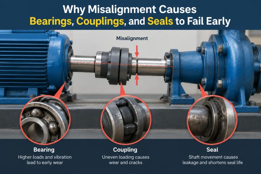

A pump has been running smoothly for months. Then its coupling insert begins shedding material, the bearing housing feels warmer than usual, and a small leak appears at the mechanical seal. These can look like three separate maintenance problems.
Often, they are three symptoms of one condition: the driver and driven machine are not rotating on the same intended centerline. Even a machine that starts and stops without obvious trouble can be transmitting damaging forces every revolution.
Misalignment is easy to underestimate because shafts can tolerate a surprising amount of error at low speed or light load. But tolerance is not the same as reliability. The components nearest the connection point must continually absorb the error.
Understanding the load path explains why bearings, couplings, and seals often fail early together—and why replacing the failed part without correcting alignment can restart the same failure cycle.
🔩 What shaft misalignment actually means
Two connected shafts are aligned when their rotational centerlines are in the required geometric relationship during operation. In a direct-coupled motor and pump, that usually means the centerlines are effectively collinear at the coupling.
Misalignment occurs when those centerlines are offset, angled, or both. The shafts may still turn, but the coupling must flex and the adjacent machine elements must react the resulting forces.
Alignment is not merely making coupling hubs “look level.” It is a measurement of shaft centerlines, made at specified locations and interpreted with allowance for machine movement in service.
📐 Parallel offset and angular error
Parallel, or offset, misalignment means the shaft centerlines are parallel but separated. Imagine two straight pencils lying side by side: they point in the same direction, yet their axes do not coincide.
Angular misalignment means the centerlines meet or would meet at an angle. A coupling can bridge a small angle, but its flexible elements must articulate once per revolution or more, depending on the design.
Most field cases contain both errors. Correcting only the visible vertical offset while leaving an angular condition can still impose substantial cyclic loading.
↕️ Vertical and horizontal planes matter separately
Misalignment has two planes. Vertical error is commonly adjusted with shims beneath machine feet, while horizontal error is corrected by moving the machine sideways.
A machine can be excellent in one plane and poor in the other. This is why a single straightedge check or a visual gap measurement cannot establish complete alignment.
For troubleshooting, separating readings by plane is useful. It helps distinguish a base, support, pipe-force, or thermal-growth problem from a simple setup error.
🔄 Why rotation turns a small error into repeated stress
At rest, a small offset can seem harmless. Once the shafts rotate, the coupling continually accommodates changing geometry. That action creates forces that repeat at shaft rotational frequency and can excite vibration in the train.
Each component sees the effect differently. A flexible coupling flexes, a bearing carries additional radial or axial load, and a seal follows shaft motion that may exceed its preferred operating conditions.
The key issue is not one dramatic overload. It is millions of repeated load cycles, often combined with heat, contamination, and normal process forces.
⚙️ The coupling is a connector, not a correction device
Flexible couplings are designed to transmit torque while accommodating limited relative movement. Their flexibility protects equipment from small residual errors and operational movement; it does not make alignment unnecessary.
When misalignment exceeds the coupling’s intended operating range, its elements bend, slide, or compress excessively. Torque transmission may continue, which can create the false impression that the coupling is healthy.
A coupling should be selected and aligned so that it has useful capacity left for thermal growth, shaft end float, and normal machine motion.
🧩 How coupling types respond differently
Different couplings tolerate error through different mechanisms, so their failure patterns differ. The manufacturer’s allowable values, speed limits, and installation instructions always govern the particular model.
| Coupling type | How it accommodates motion | Common misalignment consequence |
|---|---|---|
| Elastomeric jaw or tire | Elastic deformation of a polymer element | Heat, cracking, compression set, or element wear |
| Gear coupling | Sliding and articulation at toothed interfaces | Lubricant breakdown, tooth wear, seal leakage |
| Disc coupling | Flexing of thin metallic disc packs | Disc fatigue or bolt-hole damage |
| Grid coupling | Flexing and sliding of a spring grid | Grid wear, lubricant loss, housing damage |
“Flexible” therefore does not mean universally forgiving. A coupling’s published capacity often assumes correct assembly, suitable lubrication where required, and an operating environment within its design limits.
🔥 Heat is an early coupling warning
Excess coupling movement creates internal friction or hysteresis, which is energy lost as heat. Elastomeric elements can soften or harden with elevated temperature, while lubricated metallic couplings can lose lubricant quality.
A warm coupling is not automatically misaligned; nearby process heat, poor guarding ventilation, and normal duty can also affect temperature. But a localized temperature increase accompanied by vibration, dust, or unusual wear deserves investigation.
Temperature trends are generally more useful than a single touch-based observation. Use appropriate safety procedures and non-contact methods where rotating equipment is involved.
🛞 Bearings inherit loads they were not selected to carry
Rolling-element bearings are selected for expected radial loads, axial loads, speed, lubrication, and life targets. Shaft misalignment can add a load component that was absent from the original calculation.
The coupling transmits a force and moment into the shaft ends. Those reactions travel through the shaft to the bearings, changing how the rolling elements contact their raceways.
The result may be higher contact stress, greater friction, increased lubricant temperature, and a reduced operating margin. The bearing may fail even though its catalog capacity seemed adequate for the machine’s normal process load.
🧲 Misalignment can create axial bearing loading
Angular misalignment can generate axial forces, particularly in arrangements where coupling geometry resists shaft movement. This matters because many bearing arrangements deliberately assign axial location to one bearing while allowing another bearing to float thermally.
Unexpected thrust can overload the locating bearing or interfere with intended axial movement. In electric motors, it can also affect rotor position and increase the risk of unwanted internal contact in severe cases.
Do not assume that a radial-looking alignment error produces only radial effects. The actual load direction depends on coupling type, shaft geometry, support stiffness, and machine arrangement.
🔬 Bearing damage patterns need careful interpretation
Misalignment may contribute to uneven raceway loading, edge stress, overheating, and accelerated cage or lubricant damage. Yet bearing damage photographs alone rarely prove one root cause.
Similar-looking distress can arise from incorrect fits, poor lubrication, contamination, electrical current passage, imbalance, or housing distortion. A sound investigation combines the bearing evidence with alignment records, vibration trends, temperatures, and operating history.
Misalignment is often a contributing cause rather than the only cause. Treating it as a hypothesis to test produces better maintenance decisions than treating every failed bearing as an alignment failure.
💧 Why mechanical seals are especially sensitive
A mechanical seal controls leakage using two very flat faces that run close together: one rotates with the shaft and one remains stationary. A thin fluid film between the faces provides lubrication and cooling in normal operation.
Excess shaft movement, runout, or deflection can disturb that film. The faces may separate too far, contact too aggressively, or operate with changing contact conditions that generate heat and wear.
Seal designs vary widely, and many process pumps have specified limits for shaft deflection, runout, pressure, fluid properties, and vibration. Alignment supports these limits but cannot compensate for a bent shaft, damaged bearings, or unsuitable seal support conditions.
🌊 Seal face motion and shaft deflection
Misalignment can bend the shaft between its bearings and coupling, causing shaft motion near the seal chamber. The effect depends on shaft stiffness, overhung impeller geometry, bearing span, coupling forces, and hydraulic loading.
For a pump, the seal does not experience alignment as an abstract measurement. It experiences motion at the shaft and sleeve. That is why a pump can leak even after fitting a new seal if the underlying mechanical condition remains.
A useful diagnostic question is: did leakage begin after a seal replacement, after piping work, or after a change in operating conditions? The timing can point toward the source of movement.
🫧 Secondary seal damage and leakage paths
Mechanical seals also contain secondary sealing elements such as O-rings, wedges, or gaskets. Excessive motion, heat, or vibration can damage these components or prevent them from moving as intended during pressure and temperature changes.
Not every seal leak comes through the faces. Leakage can occur at sleeves, gland connections, stationary-seat locations, or auxiliary piping connections. Identifying the actual leak path prevents an incorrect diagnosis.
Before dismantling, observe safely: note the leak location, fluid condition, temperature, vibration history, and whether leakage changes with speed or process pressure.
📳 Vibration is both symptom and amplifier
Misalignment commonly produces vibration components related to running speed and its harmonics, but vibration signatures are not unique fingerprints. Coupling type, machine speed, structural stiffness, looseness, and other faults alter the response.
Once vibration rises, it can worsen the original condition. Fasteners may loosen, wear may increase clearances, and seal motion can grow. The system enters a feedback loop in which alignment-related forces and mechanical deterioration reinforce each other.
Vibration analysis is most valuable when interpreted alongside phase information, machine geometry, and physical inspection—not as a single automated diagnosis.
🎯 Alignment tolerance depends on the machine
A slow conveyor drive with a resilient coupling may operate acceptably with an alignment condition that would be unacceptable for a high-speed pump, compressor, or precision spindle. Speed, coupling design, bearing type, shaft span, and required reliability all matter.
There is no universal “good enough” dial-indicator reading. Target tolerances should come from the equipment manufacturer, coupling manufacturer, site reliability practice, and the machine’s actual operating behavior.
At higher speeds, small geometric errors produce more frequent flexing and can generate more demanding dynamic effects. This is why alignment targets are commonly tighter as rotational speed increases.
🌡️ Cold alignment is not always operating alignment
Machines change position as they warm. Motors, pumps, gearboxes, frames, piping, and foundations may expand at different rates and in different directions. The positions measured while cold may not be the positions present at operating temperature.
Thermal growth targets intentionally place shafts slightly offset when cold so they approach alignment during normal operation. They are based on equipment data, measured behavior, or a defensible engineering estimate.
Applying an arbitrary thermal offset is risky. Operating temperatures, mounting geometry, and support constraints can differ substantially from one installation to another.
🏗️ Soft foot undermines every measurement
Soft foot exists when one or more machine feet do not sit solidly on the base. Tightening a hold-down bolt then bends the machine frame or pulls it into a distorted position.
An alignment reading taken before soft foot is corrected may change after final tightening. The machine can also move as bolts are torqued, creating a condition that differs from the carefully measured loose-bolt position.
Check each foot systematically, correct poor shim contact or base irregularities, and verify the condition before final alignment. Clean, flat shims and clean mounting surfaces are essential.
🧱 Baseplate condition and foundation stiffness
A stable machine alignment requires a stable support. Corroded baseplates, loose grout, cracked foundations, distorted soleplates, and inadequate structural stiffness can allow the equipment to move under load.
This problem is especially misleading because alignment may be correct immediately after adjustment. It changes when the machine reaches speed, when a valve position changes, or when process piping heats.
If repeat alignments drift without a clear adjustment error, investigate the support system rather than repeatedly adding shims.
🔧 Pipe strain can move a pump after alignment
Connected piping can impose forces and moments on pump nozzles. Poor support, thermal expansion, misfitted pipe, or an unsupported valve can shift the pump casing and alter shaft alignment.
A common good practice is to verify alignment with piping disconnected where practical, then reconnect piping and check whether the machine position changes. The exact acceptance method should follow the equipment supplier’s requirements and site procedures.
Forcing pipe flanges together with bolts is not a harmless assembly shortcut. It can preload the machine before startup and create a condition that changes as the system heats.
🧰 Common alignment measurement methods
Rim-and-face dial indicators, reverse-dial setups, and laser alignment systems can all produce useful results when used correctly. The best choice depends on machine access, required accuracy, technician skill, and site practice.
Laser systems simplify geometry calculations and can guide moves in real time, but they do not correct soft foot, loose bases, damaged coupling hubs, or bad assumptions about thermal growth. Their result is only as reliable as the setup and preparation.
Basic tools still have value for rough checks, but a straightedge and feeler gauge generally cannot provide the detail needed for critical rotating equipment.
📏 Measuring the machine, not the coupling gap
Coupling hub faces may be imperfect, hubs may have runout, and shaft end float can affect readings. Good practice includes checking for obvious hub damage, verifying indicator setup, and controlling axial shaft position according to the chosen method.
The purpose is to determine relative shaft centerline positions, not simply to make a gap look uniform. Where possible, rotate shafts together during measurement to reduce the influence of eccentricity.
Document the method, readings, final foot corrections, and bolt-tightening condition. This record helps future technicians distinguish genuine machine movement from a different measurement setup.
🧭 A practical alignment workflow
- Make the equipment safe, isolated, and unable to start unexpectedly.
- Inspect the coupling, guards, base, hold-down bolts, and piping supports.
- Correct soft foot and confirm clean, sound mounting surfaces.
- Establish the intended stationary and movable machines.
- Measure initial alignment in both planes using a suitable method.
- Make vertical and horizontal corrections, then remeasure after tightening.
- Apply approved thermal-growth targets where applicable.
- Reinstall guards, start safely, and verify normal vibration, temperature, and leakage trends.
The sequence matters. Precision measurement cannot overcome a machine that rocks on its feet or is being pulled sideways by piping.
⚠️ Mistakes that produce false confidence
- Aligning before correcting soft foot: bolt torque changes the machine position afterward.
- Ignoring coupling condition: a worn element can hide or distort the relationship being measured.
- Using only cold targets: thermal movement may create operating misalignment.
- Skipping pipe-strain checks: connected piping can undo the adjustment.
- Moving the wrong machine: process connections, electrical conduit, and base constraints may make one machine the logical stationary reference.
- Stopping at a “pass” number: a result must still make physical sense for the machine and operating condition.
🧪 Distinguishing misalignment from imbalance
Imbalance occurs when the rotating mass distribution is not centered on the rotation axis. It often creates a strong vibration response at running speed, as can misalignment.
Misalignment more directly involves the relationship between connected shafts and can introduce coupling stress, directional forces, and harmonic content. In real machines, both conditions can exist at once.
Balancing a rotor will not correct a misaligned drive train. Likewise, laser-aligning shafts will not remove a heavy spot on a fan wheel or impeller.
🧯 When replacement parts keep failing
A recurring bearing, coupling, or seal failure should trigger a system-level review. Replacing the visibly damaged component may restore operation briefly while leaving the force source untouched.
For example, a hypothetical pump that receives two seal replacements in a short interval may have an unsuitable seal for the fluid—but it may also have pipe strain, bearing looseness, excessive shaft deflection, or operating misalignment. Inspection should test competing explanations.
Root-cause work is strongest when it asks what changed, what forces are present, and what evidence would disprove each suspected cause.
📈 Condition monitoring helps catch drift
Alignment is not necessarily permanent. Temperature cycles, settling grout, maintenance work, pipe modifications, impacts, and base deterioration can shift machinery over time.
Useful indicators include vibration trends, bearing temperatures, lubricant condition, coupling inspections, seal leakage observations, and repeat alignment checks after significant work. No single indicator is sufficient in every application.
Trend data is especially valuable because it shows direction. A gradual change can justify planned correction before a seal leak or bearing temperature becomes an urgent outage.
👷 Safety and maintenance boundaries
Alignment work involves heavy machines, pinch points, electrical hazards, and rotating equipment. Lockout/tagout, lifting practices, guarding requirements, and site-specific procedures are not optional details.
Some failures also require specialist input. Persistent vibration, cracked base structures, suspected shaft damage, complex compressor trains, and machinery with precise thermal targets may need reliability engineers, vibration analysts, or the original equipment manufacturer.
Good maintenance recognizes uncertainty. If measurements conflict with observed behavior, pause and investigate rather than forcing the data to fit a preferred conclusion.
✅ The core principle: align the whole operating system
Early bearing, coupling, and seal failures are frequently connected because misalignment creates a shared load problem. The coupling works harder to bridge the error, bearings carry unwanted reaction forces, and seals must tolerate increased shaft motion.
Reliable correction goes beyond moving a motor until an instrument displays a favorable value. It includes sound foundations, corrected soft foot, controlled piping forces, appropriate thermal-growth targets, correct coupling assembly, and verification after tightening and startup.
The goal is not perfect geometry in isolation; it is stable, acceptable shaft alignment under real operating conditions.
When rotating equipment is treated as a connected system rather than a collection of replaceable parts, failures become easier to diagnose and far less likely to repeat. ⚙️🔧📈