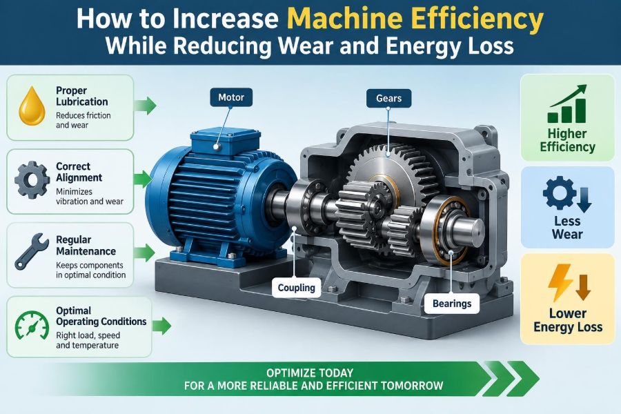

A conveyor begins to run hot near the end of a shift. A pump draws more current than it did a few months ago. A gearbox that once sounded steady now produces a faint whine. None of these changes may stop production immediately, but each can be an early sign that useful energy is being turned into heat, noise, vibration, or damage.
For a student, machine efficiency can seem like a calculation involving input and output power. For a technician, designer, or plant engineer, it is also a daily operating reality: how much product is moved, how much electricity is consumed, how often components need attention, and how reliably equipment performs.
Wear and energy loss are closely connected. Friction, misalignment, excessive load, poor lubrication, leakage, and unstable operation often consume energy before they become obvious maintenance problems. Reducing one commonly helps reduce the other.
The goal is not to chase a single maximum efficiency value in isolation. It is to make the entire machine system deliver its required duty with the least practical waste, while protecting the parts that must survive that duty over time.
🔍 Start With What Machine Efficiency Really Means
Machine efficiency is the ratio of useful output to supplied input. In simple form, it can be expressed as efficiency = useful output power / input power. A motor may receive electrical power, for example, and deliver mechanical shaft power to a pump, fan, or conveyor.
No real machine reaches perfect efficiency because some energy must be dissipated. The engineering task is to identify which losses are unavoidable for the application and which are caused by poor design, degraded condition, or unsuitable operation.
Useful output must be defined carefully. A pump that delivers more flow than the process needs is not necessarily operating efficiently at the system level, even if its internal hydraulic efficiency is respectable.
🔥 Recognize Where Input Energy Goes
Energy does not disappear; it changes form. In machines, losses commonly become heat, sound, vibration, fluid turbulence, electrical losses, or deformation of materials. Heat is especially useful as a diagnostic clue because many loss mechanisms eventually raise temperature.
A useful energy path might look like this: electrical supply, motor, coupling, gearbox, driven shaft, and final load. Every interface can add loss. Improving a highly efficient motor while ignoring a dragging belt or throttled valve may produce little overall benefit.
- Electrical resistance creates heat in conductors and windings.
- Mechanical friction heats bearings, seals, gears, and sliding surfaces.
- Fluid restrictions create pressure loss and turbulence.
- Vibration consumes energy while accelerating wear and loosening joints.
🧩 Treat the Machine as a System, Not a Single Part
Component efficiency matters, but system efficiency determines operating cost and useful performance. A correctly sized motor can still waste energy if it drives an oversized pump. A low-friction bearing cannot compensate for a shaft that is badly aligned.
Begin by mapping the complete chain from energy source to useful work. Include controls, transmission elements, fluid lines, guards that affect cooling, and the process demand. This broader view prevents a common mistake: optimizing one component while making another part of the system work harder.
For example, reducing fan speed with a suitable controller can lower air flow to match demand. Simply adding a restriction to the duct may reduce flow too, but it forces the fan to waste energy overcoming extra resistance.
📏 Measure a Baseline Before Changing Anything
Improvement without a baseline is difficult to verify. Record operating conditions before making changes: production rate, input power or current, temperatures, vibration, pressure, flow, speed, and maintenance observations. The most useful measurements depend on the machine.
Compare like with like. A compressor drawing more power on a hotter day or at higher delivery pressure is not automatically inefficient. Record load, ambient conditions, product type, and operating schedule so that later comparisons are meaningful.
A baseline also helps distinguish gradual wear from sudden faults. Trends are often more valuable than a single reading because deterioration commonly begins as a slow change in temperature, noise, or power demand.
⚖️ Match Capacity to the Actual Duty
Oversizing is often chosen to provide a safety margin, accommodate uncertainty, or allow future expansion. Some margin is sensible. Excessive capacity, however, can force a machine to operate far from its best range, where losses, control problems, and wear may increase.
Consider a pump selected for a much larger future flow than current demand. If its output is continuously throttled, energy is dissipated across the valve. If it frequently runs at very low flow, internal recirculation and temperature rise can become concerns depending on pump type and service.
Undersizing is not an answer. An overloaded motor, bearing, belt, or gear set tends to run hot and fail early. Good selection uses real duty data, expected variation, startup loads, environment, and a justified service factor.
🛢️ Use Lubrication as a Precision Tool
Lubrication forms a separating film between moving surfaces, reducing direct metal-to-metal contact. In rolling bearings, gears, chains, and sliding guides, the correct lubricant can reduce friction and transport heat away from loaded contacts.
More lubricant is not automatically better. Over-greasing a rolling-element bearing can cause churning, elevate temperature, damage seals, and consume extra energy. Too little lubricant, the wrong viscosity, or contamination can collapse the protective film and greatly accelerate wear.
Lubrication practice should specify the lubricant type, amount, application interval, delivery method, and cleanliness requirement. Those choices should come from component guidance and actual operating conditions, not from a universal schedule.
🧪 Select Viscosity for Temperature and Load
Viscosity describes a fluid’s resistance to flow. If oil is too thin at operating temperature, it may not maintain a sufficient film under load. If it is too thick, it can create drag, poor low-temperature circulation, and higher churning losses.
The right viscosity depends on speed, load, contact geometry, ambient temperature, and the machine’s lubrication arrangement. A heavily loaded, slow gear contact and a high-speed bearing do not necessarily need the same grade.
Changing lubricant solely to reduce drag can be risky. A lower-viscosity oil may decrease fluid friction but reduce protection. Evaluate operating temperature, wear evidence, and manufacturer requirements before making a change.
🧼 Keep Lubricants and Surfaces Clean
Contamination turns a lubricant into an abrasive carrier. Dust, water, process debris, degraded oil, and wear particles can score surfaces, block small passages, and interfere with oil-film formation. The result is usually both higher friction and shorter component life.
Cleanliness starts at storage. Keep containers sealed and clearly identified, use clean transfer equipment, and prevent dirt from entering during relubrication. Filters, breathers, seals, and magnetic plugs can each serve a purpose, but they must be suited to the system.
When practical, oil analysis can reveal changes in viscosity, contamination, water, or wear debris. It is a condition-monitoring tool, not a replacement for inspection or for understanding how the machine operates.
📐 Align Shafts and Couplings Carefully
Misalignment occurs when coupled shafts are not positioned along the intended common axis. It can be angular, parallel, or a combination. Flexible couplings tolerate limited movement; they do not make severe misalignment harmless.
Misalignment adds cyclic forces to bearings, shafts, couplings, and seals. It can raise vibration and temperature while requiring extra motor torque. In a severe case, a machine may appear to run normally but repeatedly consume bearings or coupling elements.
Correct alignment includes checking the machine after it is secured, accounting for thermal growth where relevant, and examining soft foot: a condition in which one machine foot does not sit flat on its base. Tightening bolts over soft foot can distort the frame and undo careful alignment.
🧱 Build a Stable Foundation and Eliminate Soft Foot
A machine needs a support structure stiff enough to maintain alignment under operating loads. Loose base bolts, cracked grout, bent mounting plates, and inadequate foundations can allow movement that appears as vibration, belt tracking problems, or repeated alignment drift.
Soft foot deserves special attention because it may be hidden until bolts are tightened. The machine frame twists as the unsupported foot is pulled down, changing shaft position and placing stress into the housing. Shims can correct a measured gap, but they should be clean, flat, and used deliberately.
Before blaming bearings for vibration, inspect the structure holding them. A sound component installed on an unstable base still experiences damaging forces.
🔄 Maintain Belts, Chains, and Gear Drives
Power transmission components must transfer torque without unnecessary slip, bending loss, impact, or tooth contact stress. Belt tension that is too low allows slip and heat; tension that is too high overloads shafts and bearings. Alignment affects both efficiency and belt life.
Chains need correct tension, lubrication, sprocket alignment, and protection from contamination. A dry or elongated chain can articulate poorly around sprockets, producing noise and uneven load transfer. Gear drives need proper backlash, contact pattern, lubrication, and housing rigidity.
| Drive element | Common waste mechanism | Practical check |
|---|---|---|
| Belt drive | Slip, misalignment, excessive tension | Inspect tracking, wear, tension, and pulley condition |
| Chain drive | Dry joints, elongation, poor sprocket engagement | Check lubrication, sag, tooth wear, and alignment |
| Gear drive | Poor lubrication, damaged teeth, incorrect mesh | Monitor oil, temperature, noise, and backlash |
⚙️ Reduce Friction Without Sacrificing Load Capacity
Friction reduction is not simply a matter of choosing the “slipperiest” material. Surfaces must carry load, resist temperature, tolerate contaminants, and survive starts and stops. The best solution depends on whether motion is rolling, sliding, oscillating, or intermittent.
Rolling-element bearings often have low running friction, but they can be vulnerable to contamination, incorrect preload, and poor mounting. Plain bearings can carry high loads and tolerate certain conditions well, but their lubrication regime is critical.
In sliding guides, consider surface finish, material pairing, lubrication access, and contact pressure. A modification that reduces friction in steady motion may perform poorly during dry starts, shock loading, or exposure to dirt.
🌡️ Use Temperature as a Condition Signal
Temperature is a powerful but incomplete indicator. A rise above the machine’s normal operating pattern can point to friction, overload, inadequate lubrication, cooling failure, electrical problems, or fluid restriction.
Compare similar points under similar conditions: one bearing housing against its counterpart, a gearbox against its historical trend, or a motor case at comparable load. A single surface temperature cannot by itself identify the root cause.
Infrared tools are useful for screening, but readings can be affected by surface finish, viewing angle, and emissivity. Confirm unusual findings with suitable contact measurements, process data, and physical inspection where safe to do so.
📳 Control Vibration Before It Becomes Damage
Vibration is motion that does not contribute to useful work. It consumes energy, fatigues structures, loosens fasteners, damages bearings, and can make precision equipment inaccurate. Common sources include imbalance, misalignment, looseness, resonance, gear defects, and hydraulic pulsation.
Vibration monitoring is most effective when it tracks a machine’s own baseline over time. A rising trend may justify inspection before the machine reaches a failure condition. The interpretation requires context because a frequency pattern can have several possible causes.
Do not attempt to balance a rotating assembly until it is mechanically sound. Loose mounts, bent shafts, worn bearings, or accumulated material can make balance corrections misleading or temporary.
🌀 Keep Rotating Parts Balanced
Unbalance exists when a rotating mass is distributed unevenly around its axis. At speed, the resulting centrifugal force increases sharply and loads bearings, shafts, housings, and foundations. Fans, grinding wheels, rotors, and pulleys are common examples.
Material buildup is a frequent practical cause. A fan may become unbalanced when dust adheres unevenly to blades; a conveyor pulley can develop issues when product accumulates on one side. Cleaning may restore acceptable operation, but the cause of buildup should also be addressed.
Balance quality should fit the machine’s speed, mass, and sensitivity. Excessive correction is not desirable, and balancing procedures should follow appropriate safety practices for rotating equipment.
💨 Design Fluid Paths to Avoid Pressure Loss
In pumping, hydraulic, pneumatic, and ventilation systems, energy is lost when fluid is forced through unnecessary restrictions. Long pipe runs, abrupt bends, undersized lines, clogged filters, partially closed valves, and poor fittings all add pressure drop.
Pressure loss requires the pump, compressor, or fan to supply more energy for the same useful delivery. It can also create turbulence, noise, cavitation risk in liquid systems, and uneven actuator performance.
Good fluid design favors appropriately sized passages, gradual transitions, sensible routing, and components selected for the required flow. The largest line is not always best: very low velocity may create other issues, while unnecessarily large systems cost more and may be hard to control.
💧 Prevent Leaks in Hydraulic and Pneumatic Systems
Leaks are direct energy losses. A hydraulic leak loses pressurized fluid and can create safety, cleanliness, and environmental problems. A compressed-air leak wastes the energy used to compress air, often without providing any useful work.
External leaks are visible or audible more often than internal leakage, which may occur across worn valves, cylinders, seals, or pump clearances. Internal leakage can cause slow actuators, heat generation, and difficulty maintaining pressure.
Fixing a leak should include finding why it occurred. Replacing a seal without correcting a scored rod, excessive side load, wrong fluid, or pressure spike often leads to repeat failure.
🎛️ Choose Controls That Match Demand
Controls can reduce waste when they allow output to follow real demand. Variable-speed drives, staged compressors, thermostatic control, and automated shutdown of idle equipment are examples. Their value depends on the load profile and the equipment’s compatibility with control changes.
A centrifugal fan or pump often benefits from speed reduction when demand falls, but a positive-displacement machine behaves differently and may require other methods. Controls should be selected based on the machine curve, process requirements, minimum safe flow or speed, and transient conditions.
Automation can also create waste if poorly configured. Frequent cycling may increase mechanical and electrical stress, while overly aggressive control loops can cause hunting: repeated oscillation around the desired setpoint.
⚡ Improve Motor and Electrical Operation
Motors lose energy through winding resistance, magnetic effects, ventilation, bearing friction, and other mechanisms. Supply imbalance, poor connections, unsuitable starting methods, overload, and inadequate cooling can increase losses and shorten insulation life.
Check that the motor is correctly selected for the duty and properly ventilated. A motor enclosed in a hot, dusty space may run at a higher temperature even when its electrical loading appears acceptable. Clean cooling passages and intact fan covers matter.
Motor efficiency should be considered with the driven load. Replacing a motor may be worthwhile in some cases, but reducing unnecessary pump head, fan resistance, or mechanical drag can provide a more fundamental improvement.
🧠 Operate Near the Best Practical Working Range
Many machines have a preferred operating region. Pumps may have a best efficiency region, engines have efficient load-speed ranges, and compressors have limits on stable or safe operation. Staying near the intended range often reduces internal losses and wear.
“Best” does not mean one fixed point for all situations. Process demand changes, ambient conditions vary, and reliability constraints may require operation away from an ideal curve. The goal is to avoid chronic operation in regions known to create recirculation, surge, overheating, stall, or excessive vibration.
Use manufacturer curves and site measurements together. Curves predict expected behavior; operating data reveal what the installed system is actually doing.
🛠️ Make Preventive Maintenance Condition-Based
Time-based maintenance is useful for tasks with known service intervals, but it can lead to unnecessary work or missed emerging faults. Condition-based maintenance uses observable indicators—such as vibration trend, oil condition, temperature, ultrasound, electrical signature, or inspection findings—to guide action.
The right approach is often a combination. Safety-critical items may need scheduled inspection regardless of apparent condition, while large rotating assets can justify more detailed monitoring. The complexity should match the consequences of failure and the value of the asset.
Record what was found and what was changed. Maintenance history turns individual repairs into information that can reveal recurring design, operating, or training issues.
🧰 Standardize Installation and Repair Quality
A high-quality replacement part can fail quickly if installed incorrectly. Bearing mounting force applied through the rolling elements, damaged shaft fits, contaminated grease, incorrect torque, and poorly seated seals all introduce early failure mechanisms.
Written work instructions are especially valuable for repeatable tasks. They can specify cleaning, inspection points, tools, heating methods, torque values, alignment checks, lubrication quantities, and acceptance measurements.
Standardization is not bureaucracy for its own sake. It reduces variation in work that directly affects friction, preload, alignment, and reliability. It also makes it easier to train new personnel and investigate failures objectively.
🧑🔧 Train Operators to Notice Small Changes
Operators are often the first people to hear a new sound, notice a slow response, see a leak, or feel an abnormal temperature through a safe external surface. Their observations can prevent a minor efficiency loss from developing into downtime.
Training should give people clear boundaries. They need to know which observations to report, which actions are permitted, and when equipment must be isolated rather than adjusted while running. Never encourage unsafe inspection around exposed moving parts or energized equipment.
A simple shift log can capture useful details: unusual noise, repeated resets, product buildup, fluid level changes, odor, heat, and process instability. Specific observations are more actionable than “machine seems bad.”
🚫 Avoid Common Efficiency “Fixes” That Backfire
Some quick fixes merely move the problem. Increasing belt tension can stop slip while overloading bearings. Adding grease can quiet a noisy bearing temporarily while creating overheating. Closing a valve may control flow while wasting pump energy.
- Do not increase speed without checking torque, balance, cooling, and structural limits.
- Do not substitute lubricants based only on appearance or convenience.
- Do not silence alarms or bypass protective devices to maintain output.
- Do not treat vibration, heat, or leakage as normal without establishing a cause.
Effective improvement targets the mechanism creating loss, not just the most visible symptom.
🧮 Prioritize Changes by Loss, Risk, and Feasibility
Not every opportunity deserves the same effort. Start with conditions that combine high energy use, rapid wear, safety implications, production impact, or a clear deviation from normal operation. A hot, misaligned pump train may deserve attention before a minor cosmetic improvement.
Estimate the likely mechanism, the cost and disruption of correction, and how results will be measured. Low-cost actions such as repairing leaks, cleaning coolers, correcting alignment, or removing product buildup can sometimes produce meaningful gains quickly.
For larger projects, test assumptions. A proposed variable-speed drive, redesign, or component upgrade should be evaluated against the actual duty cycle and process needs, not only its theoretical potential.
📊 Verify Results and Keep Learning
After an intervention, compare performance against the original baseline under similar conditions. Look at more than one indicator: energy input, output rate, temperature, vibration, leak rate, maintenance frequency, and product quality can all reveal whether the change worked as intended.
Some benefits take time to become visible. A better lubrication practice may show up first as lower temperature and cleaner oil, then later as fewer component replacements. Conversely, an immediate power reduction that creates reliability problems is not a complete success.
Document both successful and unsuccessful trials. Engineering improvement is iterative: measure, understand, change, verify, and refine.
🧭 Build Efficiency Into Design Decisions
The cheapest time to avoid energy loss and wear is often before the machine is installed. Provide access for alignment and lubrication, allow space for cooling and inspection, specify appropriate seals and filtration, and design piping or ducting with real operating demand in mind.
Designers should also consider maintainability. A component that is difficult to inspect or service correctly is more likely to be neglected or repaired inconsistently. Clear datum surfaces, accessible fasteners, lifting provisions, and sensible sensor locations support long-term performance.
Operational efficiency is therefore a lifecycle issue. Purchasing cost, installation quality, energy use, maintenance labor, spares, and downtime all influence the practical value of a machine.
✅ The Core Principle: Reduce Losses at Their Source
The most durable efficiency gains come from understanding where energy is being lost and correcting the physical cause. Friction calls for appropriate surfaces, lubrication, alignment, and loading. Fluid losses call for sensible flow paths, leak control, and demand matching. Electrical losses call for sound motor operation, connections, cooling, and controls.
There is no single universal upgrade. A well-lubricated but oversized pump, a premium motor driving a slipping belt, or a carefully aligned machine operating against a blocked filter can still waste energy. The machine must be assessed as an interacting system.
When measurement, maintenance, design, and operation work together, improved efficiency and reduced wear become complementary outcomes rather than competing goals.
Make every unit of input energy do useful work for as long as possible, and machine efficiency will improve while wear and avoidable loss decline. ⚙️🔧📉