
A bookshelf loaded with textbooks may sag at its center. A bicycle frame flexes slightly over a rough road. Tightening a bolt stretches it, even though the movement is far too small to see.
These are not signs that engineering has failed. They are reminders that no real material is perfectly rigid. Whenever a force acts on a part, the part responds by changing shape or size to some degree.
That response determines whether a bridge feels stable, whether a machine remains accurate, and whether a component eventually cracks. Engineers need more than the question, “Will it break?” They must ask how much it will deform, where the deformation will concentrate, and whether it will recover when the load is removed.
Stress and strain provide the language for answering those questions. Once the distinction is clear, many everyday mechanical behaviors become easier to predict.
🧱 Materials Are Not Perfectly Rigid
In introductory sketches, supports, beams, and machine parts are often drawn as unchanged under load. This simplification helps isolate forces, but it is not physically exact. Atomic bonds stretch, compress, rotate, and slide when a material is loaded.
A steel shaft may deform by only micrometres, while a rubber seal may deform by millimetres. Both are deforming. The difference lies in their geometry, loading, and material stiffness.
Deformation is not automatically damage. Controlled deformation is essential in springs, suspension systems, seals, clamps, and many energy-absorbing structures.
🎯 Load Is the Starting Point
A load is an external action applied to a body. It may be a force, a moment, pressure, temperature change, or a combination of these effects. A hanging weight pulls; a hydraulic cylinder pushes; a rotating motor shaft experiences twisting.
Where and how a load is applied matters as much as its magnitude. The same force can be harmless when spread across a large area and harmful when concentrated at a small contact point.
- Static loads are applied slowly or remain roughly constant.
- Dynamic loads vary with time, such as vibration or repeated wheel impacts.
- Impact loads act over a very short time and can produce high local effects.
- Thermal loads arise when restrained parts try to expand or contract.
📏 Stress Measures Internal Force Intensity
When an external force acts on a component, internal forces develop to keep its material in equilibrium. Stress describes how intensely those internal forces are distributed over an area.
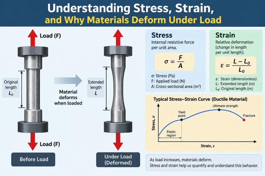
For a simple axial load, average normal stress is written as σ = F / A, where σ is stress, F is the axial force, and A is the cross-sectional area resisting it.
The usual SI unit is the pascal, or newton per square metre. Because engineering stresses are commonly much larger than one pascal, megapascals (MPa) and gigapascals (GPa) are frequently used.
↔️ Normal Stress Pulls or Pushes
Normal stress acts perpendicular to a chosen cross-sectional area. A bar pulled from both ends carries tensile stress. A column pressed from both ends carries compressive stress.
Imagine two people pulling a rope: its fibers are under tension. Now imagine pressing a foam block between your hands: its material is under compression. Metals, concrete, polymers, and wood all respond differently to these two conditions.
Concrete is generally much stronger in compression than in tension, which is one reason reinforced concrete includes steel reinforcement where tensile stresses are expected.
✂️ Shear Stress Encourages Sliding
Shear stress acts parallel to an area rather than perpendicular to it. It tends to make neighboring layers of material slide past one another.
Scissors cut by applying shear near their blades. A bolt joining two overlapping plates may be loaded in shear if the plates are pulled in opposite directions. Adhesive joints and punched sheet-metal parts also require careful shear-stress assessment.
For an idealized direct-shear case, average shear stress is often expressed as τ = V / A, where V is the shearing force. Actual shear-stress distributions can be nonuniform, especially near holes, joints, and changing geometry.
🔄 Torsion Produces Shear Through Twisting
Torsion occurs when a torque twists a member about its longitudinal axis. Drive shafts, screwdriver bits, drill shanks, and torsion bars are familiar examples.
A shaft under torque does not merely “feel a twist.” Its cross-sections rotate relative to one another, and shear stress develops throughout the section. In a circular shaft, this stress is usually greatest near the outside surface and lowest at the center.
This explains why material located far from the centerline is especially valuable for resisting torque. It also helps explain the efficiency of hollow shafts in applications where weight matters.
🌉 Bending Creates Tension and Compression Together
A beam loaded sideways bends. One side becomes shorter and experiences compression, while the opposite side becomes longer and experiences tension. Between them lies a location called the neutral axis, where longitudinal bending stress is ideally zero.
Consider a simply supported ruler pushed down at its middle. Its top surface is compressed and its bottom surface is stretched. Flip the loading direction, and the stressed sides reverse.
Bending stress generally increases with distance from the neutral axis. That is why I-beams place much of their material in flanges far from the center, while the thinner web mainly transfers shear.
📐 Strain Measures Relative Deformation
Stress describes internal force intensity. Strain describes deformation relative to an original dimension. For a bar in uniform axial loading, normal strain is ε = ΔL / L₀.
Here, ΔL is the change in length and L₀ is the original gauge length. Because it is a ratio of lengths, strain has no physical unit, although it may be reported as a decimal, percentage, or microstrain.
A 1 mm extension is not equally significant for every part. On a 10 mm feature it is substantial; on a 10 m cable it is comparatively small. Strain captures that distinction.
🧮 Stress and Strain Are Not Interchangeable
Stress is related to the internal loading state. Strain is the resulting change in shape or size. A material can experience high stress with small strain if it is stiff, or modest stress with large strain if it is compliant.
| Concept | What it describes | Typical unit | Simple question |
|---|---|---|---|
| Stress | Internal force per area | Pa, MPa, GPa | How intensely is the material loaded? |
| Strain | Relative deformation | Unitless, %, microstrain | How much has it changed shape or size? |
| Stiffness | Resistance of a part to deformation | Depends on system | How much force is needed for a given deflection? |
Confusing these terms leads to poor communication. A component does not “have stress” in the same fixed sense that it has density; its stress depends on the applied loading and boundary conditions.
📈 The Stress–Strain Curve Tells a Material Story
A tensile test gradually pulls a prepared specimen while force and extension are measured. Converting the measurements to stress and strain gives a stress–strain curve, which summarizes how that material behaves under that specific test condition.
The curve is not a universal property independent of everything else. Results can be influenced by temperature, loading rate, specimen orientation, manufacturing history, and the chosen test method.
Even so, the curve is one of the most useful tools in materials engineering because it distinguishes elastic response, permanent deformation, strength, and fracture behavior.
🪀 Elastic Deformation Is Recoverable
Within an elastic range, a material returns approximately to its original dimensions after the load is removed. A carefully designed spring relies on this behavior every time it is compressed or extended.
For many metals at relatively small strains, stress and strain are approximately proportional. This relationship is commonly written as σ = Eε, where E is Young’s modulus, also called the elastic modulus.
A high modulus means the material strains less under a given stress. It does not, by itself, mean the material is stronger or harder to fracture.
🧲 Young’s Modulus Describes Material Stiffness
Young’s modulus is a material property that reflects resistance to elastic axial strain. Steel has a much higher elastic modulus than most common polymers, so an equally shaped steel member usually stretches less under the same axial load.
However, part stiffness depends on more than modulus. A long, thin steel rod can be easier to stretch than a short, thick polymer part because geometry is also decisive.
For a uniform axial member, extension is approximated by ΔL = FL / AE. This simple expression shows the competing effects clearly: more force and greater length increase extension, while more area and a higher modulus reduce it.
🧠 Stiffness, Strength, and Hardness Differ
These terms are often used casually as if they mean the same thing. In engineering, they answer different questions.
- Stiffness is resistance to elastic deformation.
- Strength is resistance to yielding, fracture, or another defined failure mode.
- Hardness is resistance to localized indentation, scratching, or penetration.
- Toughness is the ability to absorb energy before fracturing.
Glass, for example, can be stiff and hard but relatively brittle. A ductile metal may be less hard yet much more tolerant of deformation and energy absorption before it fractures.
🛠️ Plastic Deformation Leaves a Permanent Change
When loading exceeds a material’s elastic limit, some materials begin to deform permanently. This is plastic deformation. Remove the load, and the part recovers its elastic portion of deformation but retains a residual shape change.
Bending a paper clip until it stays bent is an everyday demonstration. Metal forming processes such as rolling, stamping, forging, and bending deliberately use plastic deformation to create useful shapes.
Plasticity is not always undesirable. It can redistribute stress locally and provide warning before failure. But it is unacceptable when a precision mechanism must maintain alignment or when a pressure boundary must retain a specified shape.
🚦 Yielding Marks a Design Threshold
Yield strength is commonly used to indicate the stress level at which noticeable permanent deformation begins under a specified test convention. For many ductile metals, designers use it as a central limit in static-strength calculations.
Not every material has a sharp, obvious yield point. In such cases, a proof stress based on a prescribed small permanent strain may be reported instead. The exact interpretation depends on the material and test practice.
A component can remain intact after yielding yet still be unfit for service. A bent bracket, stretched bolt, or distorted gear housing may no longer meet its functional requirements.
💥 Ultimate Strength and Fracture Are Later Events
On a typical ductile-metal tensile curve, stress rises after yielding until it reaches a maximum called the ultimate tensile strength. Beyond that point, localized thinning, or necking, can begin in a tensile specimen.
Fracture occurs when the material separates. The fracture stress and appearance depend on the material, flaw population, geometry, temperature, loading rate, and stress state.
Designing only against ultimate strength can be misleading. A component may yield, buckle, fatigue, or become excessively flexible long before it reaches a simple tensile fracture limit.
🧊 Brittle and Ductile Failures Look Different
Ductile materials often undergo substantial plastic deformation before fracture. This can offer visible warning, such as elongation, necking, or permanent bending.
Brittle materials may fracture with little macroscopic plastic deformation. Ceramics, glass, and some hardened metals are more sensitive to cracks and tensile stress concentrations than a simple strength number suggests.
Neither behavior is universally better. A turbine blade, a crash structure, a cutting tool, and a ceramic electrical insulator require different balances of stiffness, strength, toughness, temperature capability, and wear resistance.
🕳️ Stress Concentrations Change the Local Picture
The equation σ = F / A gives an average stress. Real parts often have local peaks near holes, threads, sharp inside corners, keyways, weld toes, and abrupt changes in section.
These stress concentrations matter because cracks and yielding often initiate where local stress is highest. A plate with a hole can have a much higher stress around the hole edge than its nominal average stress suggests.
Good design frequently uses generous fillets, smooth transitions, appropriate surface finish, and careful feature placement to reduce concentrated stress.
🪚 Notches Matter More Under Repeated Loading
A notch does not automatically cause failure. Its severity depends on the material’s ductility, the local stress state, manufacturing quality, and the applied load history.
Under repeated loading, however, a notch can become a preferred location for fatigue crack initiation. Small machining marks or corrosion pits may play a similar role when stresses cycle many times.
Sharp geometry is sometimes unavoidable. In those cases, the engineer may increase local section size, improve the surface, alter the load path, select a more fatigue-tolerant material, or inspect the feature during service.
🔁 Fatigue Can Fail Parts Below Static Strength
Fatigue is progressive damage caused by repeated or fluctuating stress. A part can fail after many cycles even when each individual load is below its static yield strength.
Rotating shafts, aircraft structures, springs, gears, and welded machine frames are typical fatigue-sensitive components. The danger is that cracks can grow gradually from a small initiation site before final fracture occurs suddenly.
Fatigue design requires load spectra, mean stress, geometry, surface condition, environment, and material data that fit the intended application. A single “safe stress” rarely captures the whole problem.
⏳ Creep Depends on Time and Temperature
Creep is time-dependent permanent deformation under sustained load. It becomes especially relevant at elevated temperatures, although some polymers can creep noticeably even near ordinary service temperatures.
A loaded plastic shelf that slowly sags over months illustrates the basic idea. High-temperature piping, turbine components, and furnace fixtures require more specialized creep assessment because long exposure can alter microstructure and strength.
A part that passes a short-term strength test may still be unsuitable for long-duration service. Service temperature and expected life must be part of material selection.
🌡️ Temperature Can Create Stress Without External Force
Most materials expand when heated and contract when cooled. If this movement is free, thermal strain may occur with little stress. If movement is restrained, significant thermal stress can develop.
A metal bar fixed rigidly at both ends and heated wants to lengthen. The restraints prevent that expansion, so compressive stress builds. Cooling a restrained bar creates the opposite tendency.
Expansion joints in piping and bridges, gaps in rails, and flexible mounting strategies exist because thermal movement must be accommodated rather than ignored.
💧 Environment Changes Material Response
Moisture, corrosion, ultraviolet exposure, chemicals, and temperature cycling can change material behavior over time. A material that performs well in a dry indoor test may behave differently outdoors, in seawater, or near aggressive chemicals.
Corrosion can remove material and create pits that intensify local stress. Some polymers absorb moisture or soften at elevated temperature. Certain metal-environment combinations can experience forms of environmentally assisted cracking.
Material data should therefore match the expected environment whenever possible. A nominal room-temperature property is only one part of a service assessment.
🧭 Direction Matters in Many Materials
Some materials are approximately isotropic, meaning their properties are similar in different directions. Others are anisotropic, meaning direction changes their response.
Wood is much stronger and stiffer along its grain than across it. Rolled metals can show directional behavior because of their processing history. Fiber-reinforced composites are deliberately strongest along fiber directions.
Ignoring direction can produce an unsafe or overly flexible design. Composite laminates, in particular, must be analyzed with load paths and fiber orientations considered together.
📦 Geometry Often Controls Deflection
Material choice is only half of stiffness design. Shape can transform performance. A flat strip and an I-section made from the same material may have dramatically different bending stiffness because their material is distributed differently.
In bending, moving material away from the neutral axis increases resistance to curvature. In buckling, increasing section shape efficiency can improve stability without simply adding solid mass.
This is why thin-walled tubes, corrugated panels, ribs, and folded sheet forms appear so often in engineering. They use geometry to gain stiffness efficiently.
🏛️ Compression Members Can Buckle Before Crushing
A slender column under compression may fail by suddenly bending sideways, a phenomenon called buckling. This can occur at stresses well below the material’s compressive strength.
Try pressing a short drinking straw and then a long one between your fingers. The longer one is much more likely to bow sideways. End restraint, straightness, load alignment, and cross-sectional shape all affect buckling resistance.
For columns, checking compressive stress alone is not enough. Stability is a separate design requirement.
🔩 Bolts Use Preload to Control Joints
When a bolt is tightened, it stretches elastically and creates clamp force between jointed parts. This initial tension is called preload.
A properly preloaded joint can keep mating surfaces compressed so that service loads are transferred by friction or controlled bearing, rather than allowing repeated opening and bolt bending. The exact joint behavior depends on stiffness, load direction, friction, and assembly method.
Overtightening can yield or damage threads; undertightening can permit slip, loosening, or fatigue. Torque is an indirect and variable indicator of preload because friction consumes much of the applied turning effort.
🧪 Material Tests Need Interpretation
Tensile, compression, bending, hardness, impact, creep, and fatigue tests each reveal a different aspect of behavior. No single test fully describes every service condition.
Test coupons are controlled specimens, while real components include surface finish, welds, residual stresses, assembly variation, and complex load paths. Engineers use test data as evidence, then apply analysis, standards, safety factors, and validation appropriate to the consequence of failure.
For critical equipment, physical testing, inspection, and monitoring may be needed alongside calculations. A neat equation is valuable, but it is not a substitute for understanding the actual system.
💻 Simulation Helps, but Assumptions Still Matter
Finite element analysis can estimate stress, strain, contact pressure, temperature effects, and deformation in complex geometry. It is especially useful where hand calculations are too simplified.
Yet a colorful stress plot is only as reliable as its inputs. Incorrect constraints, unrealistic contacts, poor mesh quality, or an unsuitable material model can produce precise-looking but misleading results.
- Check that reactions balance applied loads.
- Refine the mesh where stress gradients are expected.
- Distinguish meaningful hot spots from numerical singularities at idealized sharp constraints.
- Compare results with simple hand estimates and physical behavior.
⚠️ Common Mistakes in Stress and Strain Problems
A frequent mistake is using the original cross-sectional area after large deformation without recognizing the limitation. Engineering stress is useful for many design calculations, but true stress may better describe material behavior at substantial strain.
Another mistake is treating a material-property value as a guaranteed component limit. Manufacturing variation, geometry, temperature, defects, and load uncertainty all affect real performance.
Also avoid assuming that zero visible deformation means zero strain. Many important elastic strains are too small to see but large enough to affect alignment, sealing, vibration, or measurement accuracy.
🧰 A Practical Workflow for Checking a Part
A useful first pass begins by defining the job of the part, the loads it will see, and what counts as unacceptable behavior. Failure may mean fracture, yielding, excessive deflection, leakage, fatigue cracking, buckling, or loss of alignment.
- Identify load cases, directions, supports, and likely misuse conditions.
- Find critical sections and likely stress concentrations.
- Estimate nominal stresses and deflections with suitable mechanics models.
- Compare results with material limits and service requirements.
- Check additional modes such as fatigue, buckling, creep, wear, and thermal expansion.
- Validate assumptions through testing, inspection, or more detailed analysis when consequences justify it.
This sequence is not a substitute for professional design review, especially for safety-critical equipment. It is a disciplined way to avoid overlooking the basic mechanics.
🔍 Reading Everyday Objects Like an Engineer
Look at a cantilevered sign bracket: its fixed end is usually the critical bending region. Look at a wrench: its handle is shaped to resist bending while remaining comfortable and light. Look at a plastic bottle: ribs and curved surfaces add stiffness without requiring a thick wall.
These objects reveal a central design habit: engineers guide stress through material rather than merely adding material everywhere. Load paths, geometry, joints, and expected deformation are designed together.
When an object appears oversized in one region and thin in another, ask what load it carries. The answer is often visible in its form.
✅ The Core Principle: Load, Shape, Material, Response
Stress and strain connect four questions that should always be considered together: What load acts? What is the part’s geometry? What material is used? How does the part respond?
Stress indicates where internal loading is intense. Strain indicates how much relative deformation results. Material properties describe the response, while geometry and constraints determine how those properties appear in a real component.
Good mechanical design is not about making every part rigid or strong; it is about ensuring that deformation and failure modes remain acceptable throughout the intended service life.
Once stress and strain are viewed as a linked cause-and-response pair, sagging shelves, twisting shafts, tightening bolts, and flexing bridges stop being separate mysteries. They become different expressions of the same mechanics—loads acting through materials and geometry. ⚙️📐🔧