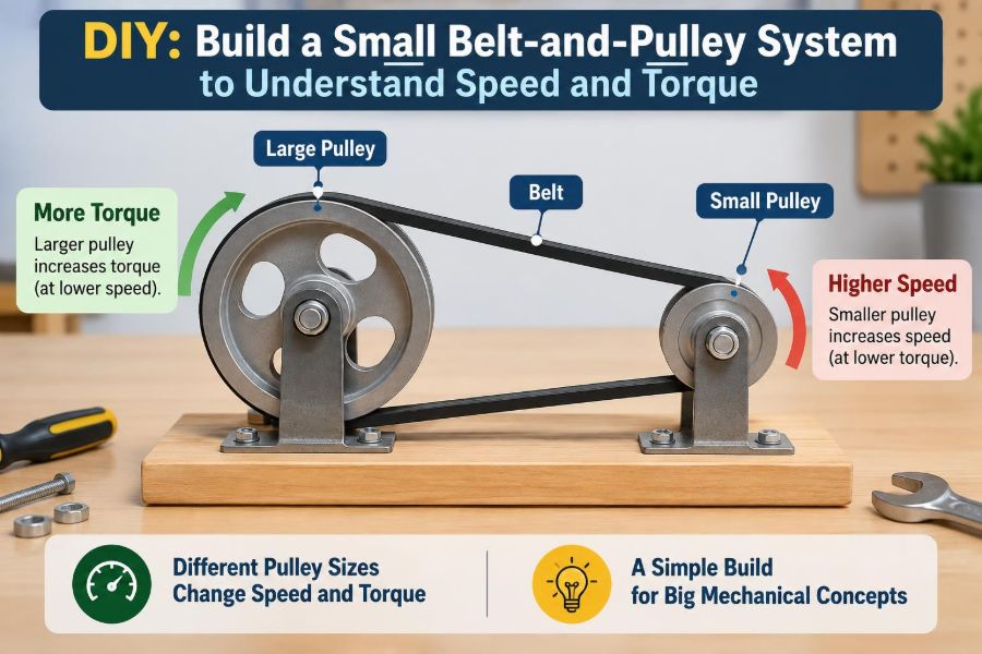

A belt-and-pulley drive is easy to overlook because it is hidden inside so many familiar machines. It turns a fan, spins a drill press, drives workshop equipment, and once helped transfer power throughout factories before electric motors became common at every workstation.
Yet the same simple arrangement answers a question that appears across mechanical engineering: if a motor spins quickly but a load needs more turning force, what can be changed without replacing the motor?
A small bench-top model makes the answer visible. By moving a belt between differently sized pulleys, you can watch rotational speed change, feel the difference in resistance at the output shaft, and learn why a system that seems mechanically simple still needs careful alignment and tension.
This project is not a high-power machine. It is a controlled demonstration of speed ratio, torque, friction, and losses—the ideas behind many real power-transmission systems.
🎯 Set a clear learning goal
The aim is to build a safe, low-speed belt drive with a driving pulley and a driven pulley. The driver is attached to the input, such as a hand crank or small DC motor. The driven pulley receives motion through the belt.
Your model should let you interchange pulley sizes. That single feature turns a craft project into an experiment: hold the input speed roughly constant, change the pulley combination, and compare output speed and turning force.
🧠 Understand what pulleys actually change
Pulleys do not create power. They trade rotational speed for torque, while real systems also lose a small amount of power through belt flexing, bearing friction, air resistance, and slip.
A small driver turning a large driven pulley slows the output but increases available output torque. A large driver turning a small driven pulley does the opposite: it produces a faster output, but less torque for a given input torque.
Think of bicycle gears. A low gear makes pedaling easier when climbing, but the wheel turns fewer times per pedal revolution. A belt drive makes the same kind of exchange.
🔄 Define speed, torque, and power
Rotational speed describes how fast a shaft turns, often in revolutions per minute, or rpm. Torque is turning effect: the tendency of a force to rotate an object about an axis. Its SI unit is the newton-metre, N·m.
Mechanical power depends on both torque and angular speed. In ideal form, power equals torque multiplied by angular speed. Therefore, reducing speed can allow torque to rise, but not without limit and not without losses.
For this model, you do not need a precision torque meter. A light cord wrapped around the output shaft and attached to a small known mass can provide a useful qualitative test.
🧰 Gather practical materials
Choose components that are easy to mount and unlikely to cause injury. A hand crank is especially useful because it keeps speeds low and gives direct feedback on changing load.
- A rigid wood, acrylic, or metal baseboard
- Two shafts, such as bolts, smooth rod, or hobby shafts
- Two pulley sets of different diameters
- An elastic belt, O-ring, round belt, or suitable flat belt material
- Simple shaft supports, bearings, bushings, or drilled blocks
- Washers, nuts, spacers, screws, and a small adjustable mounting plate
- A hand crank or low-voltage DC motor with an appropriate power source
- Ruler, marker, drill, and basic hand tools
Avoid brittle, cracked, or sharply edged parts. The model works best when its structure is stiff enough that the shafts do not move noticeably under normal belt tension.
🛑 Build for low-speed safety first
Even a small pulley can catch loose hair, sleeves, jewelry, or a dangling cable. Keep the apparatus low speed, secure it to the bench, and do not adjust the belt while the input is turning.
If you use a motor, select a low-voltage unit and use a power source suited to it. Disconnect power before changing pulleys or correcting alignment. A hand-driven version is often the best starting point for classroom demonstrations.
Do not treat this model as a lifting device. Its parts, fasteners, belt grip, and frame are not engineered or rated for lifting people or substantial loads.
📐 Choose pulley diameters deliberately
Start with a pair that has a clear difference in diameter, such as a 20 mm driver and a 60 mm driven pulley. Exact dimensions are less important than measuring the effective diameter consistently.
For a belt running near the outside of a pulley, the relevant dimension is the pitch diameter: approximately the diameter where the belt’s tension-carrying centerline travels. With thin, flexible belts in a simple experiment, outside diameter is often an acceptable approximation, provided you acknowledge the limitation.
🧮 Calculate the ideal speed ratio
For a belt drive without slip, belt speed is the same at both pulleys. That produces the familiar relation:
n₁D₁ = n₂D₂Here, n is rotational speed and D is pulley diameter. Subscript 1 refers to the driver; subscript 2 refers to the driven pulley. Rearranging gives:
n₂ = n₁ × D₁ / D₂If a 20 mm driver rotates at 120 rpm and drives a 60 mm pulley, the ideal output speed is 40 rpm. The driven pulley completes one revolution for every three revolutions of the driver.
⚖️ Estimate the torque trade
Ignoring losses, torque changes in the inverse direction to speed. A speed reduction of 3:1 ideally multiplies output torque by about three. In practice, the output torque will be lower because the system is not perfectly efficient.
The useful rule is: small driver to large driven pulley means lower speed and higher torque. It is an idealized relationship, not a guarantee that the output can turn any chosen load. Belt friction, shaft strength, motor capability, and pulley attachment all set limits.
📋 Compare common pulley arrangements
| Driver and driven arrangement | Output speed | Output torque tendency | Typical use |
|---|---|---|---|
| Same diameter | Approximately unchanged | Approximately unchanged | Simple motion transfer |
| Small driver, large driven | Reduced | Increased | Loads needing easier turning |
| Large driver, small driven | Increased | Reduced | Light, faster rotating loads |
“Increased” and “reduced” refer to the output relative to the input under the same idealized operating conditions. Real losses and slip can make the observed values differ.
🪚 Make a rigid adjustable base
Mount one shaft support in a fixed position and the other on a slotted plate or sliding block. Adjustment lets you fit a belt, set tension, and test belts of different lengths without remaking the whole frame.
The two shaft centerlines should remain parallel as the spacing changes. A base that flexes or a sliding mount that twists makes alignment difficult and can cause a belt to wander.
🧭 Set the shafts parallel
Place a straightedge across the pulley faces or use a ruler to compare spacing at the front and rear of each pulley. The shafts should be parallel, and the pulley grooves or rims should sit in the same plane.
Misalignment creates sideways belt force. That force wastes energy, accelerates wear, may pull a belt off the pulley, and can make a useful demonstration look inconsistent.
🔩 Secure pulleys to their shafts
A pulley must rotate with its shaft rather than slipping around it. Commercial pulleys may use set screws, hubs, keys, or clamping arrangements. In a lightweight prototype, a carefully fitted shaft, washers, and a retaining nut may be sufficient.
Check the connection by holding the shaft and gently trying to rotate the pulley. Any unnoticed hub slip will imitate belt slip and confuse your measurements.
🪢 Select a belt that suits the experiment
Round elastic belts and O-rings are forgiving for small DIY rigs. They tolerate modest pulley imperfections and can be installed easily. Flat belts provide a useful view of belt tracking, but generally need more careful alignment.
A toothed belt and matching toothed pulleys can eliminate normal friction-driven slip, but it demonstrates a different class of drive. For understanding friction, tension, and slip, a smooth belt is more revealing.
↔️ Set belt tension without overdoing it
A belt needs enough initial tension to develop frictional grip. If it is too loose, the driver turns while the belt creeps or slips over the pulley. If it is too tight, shaft supports see excessive radial load and turning the system becomes unnecessarily difficult.
For a small model, press lightly at the middle of the longer belt span. A modest, repeatable deflection is more useful than trying to force a universal numerical rule; belt material, span length, and pulley size all matter.
After a few turns, recheck tension. Elastic belts often settle after installation.
👀 Identify the tight side and slack side
When power flows through a belt, one span carries greater tension than the other. The higher-tension span is the tight side; the lower-tension span is the slack side. Their tension difference transmits torque.
In a hand-cranked model, gently pinch the belt only when stationary and compare how each span feels after loading the output. The difference may be subtle, but the idea explains why tension alone is not the whole story: it is the difference in tension that produces useful turning effect.
🔁 Use an open belt for the basic build
An open belt connects pulleys so they rotate in the same direction. This is the simplest layout and should be your baseline configuration.
A crossed belt causes the driven pulley to rotate in the opposite direction. It can be an interesting extension, but the twist adds rubbing and is less suitable for short, compact layouts. Establish reliable results with the open belt first.
✋ Add a hand crank or motor input
A hand crank gives a direct sense of torque. When you attach a modest output load, you will feel increased resistance at the input. With a reduction ratio, the crank turns farther for each output revolution, but the output can apply more turning force.
A motor makes speed comparison easier if its input voltage is held steady. However, many small DC motors change speed noticeably as load changes. Treat a stated no-load motor speed as a rough reference, not as the speed it will necessarily maintain in the experiment.
🏷️ Measure speed with a simple marker
Put a bright tape mark or drawn line on each pulley rim. Count revolutions over a timed interval, or record a short video and count frames if available. Longer timing intervals reduce the effect of a one-revolution counting error.
For example, compare 30 seconds of input and output turns. Divide each count by the time to calculate revolutions per second, then multiply by 60 for rpm. Repeat the measurement and use the average if your hand-crank speed varies.
🧪 Run a no-load baseline test
Before adding a load, record pulley diameters, belt type, center distance, and approximate input and output speeds. This is your baseline.
Compare the measured output speed with the ideal ratio. Small differences can arise from imperfect timing, belt thickness, pulley geometry, and slip. A large difference usually indicates a setup problem worth investigating.
🏋️ Test output torque cautiously
To compare torque qualitatively, attach a small drum or spool to the output shaft and wrap a cord around it. Hang a light mass or apply a gentle spring scale pull at a known drum radius. Increase load gradually.
Torque is force times perpendicular radius. If a 1 N force acts tangentially at a 0.02 m radius, the applied torque is 0.02 N·m. Keep forces small and prevent any falling mass from striking feet, equipment, or the belt drive.
Compare pulley configurations using the same drum and the same controlled input. The reduction setup should resist a greater output load before stalling or slipping, though exact results depend on input torque and losses.
📉 Recognize belt slip
Slip occurs when the belt slides relative to a pulley instead of maintaining the expected rolling contact. The output then turns slower than the ideal ratio predicts, and the belt may heat, polish, or leave visible wear.
Mark both the pulley and belt with aligned temporary lines. After running under load, separated marks reveal relative movement. This is more reliable than judging slip by sound alone.
Slip is not always a failure; it can protect a system from overload. But in this experiment, it means the simple no-slip speed equation no longer describes actual motion accurately.
🧼 Improve grip before increasing tension
If a clean, correctly aligned belt slips under a light intended load, first verify pulley attachment, belt condition, and wrap angle. A small pulley with little belt contact has less frictional opportunity to transfer torque than a larger wrapped contact path.
Increase tension in small steps only after these checks. Excessive tension may hide the immediate symptom while increasing bearing friction and bending the base. Replacing a glossy, contaminated, or aged belt is often the better remedy.
📏 Understand wrap angle
Wrap angle is the angle through which the belt contacts a pulley. A pulley receiving more belt contact generally has a greater ability to transmit torque before slipping, assuming comparable belt and surface conditions.
With very unequal pulleys and a short center distance, the belt wraps only a small arc of the smaller pulley. Moving shafts farther apart can improve that geometry, although it requires a longer belt and changes the structure of the model.
🔥 Account for real-world losses
Your ideal ratio predicts kinematics: the geometric relationship between speeds. It does not guarantee perfect power transfer. Bearings rub, belts bend repeatedly, shafts may wobble, and air resistance rises as components move faster.
These effects appear as heat, sound, reduced output, or a need for more input effort. In a small system the losses may be hard to isolate, but noticing them is valuable. Mechanical design involves deciding whether a loss is acceptable, reducible, or evidence of a fault.
🧱 See why pulley material matters
Wood, plastic, metal, and 3D-printed pulleys can all work in a demonstration, but their surfaces and stiffness differ. A rough or eccentric pulley causes vibration and varying belt tension. A flexible pulley may deform under belt load and change tracking.
Measure a homemade pulley in several directions. If its diameter varies significantly, the output speed can fluctuate during each revolution. That is not merely an inconvenience—it shows why concentricity matters in rotating machinery.
🛠️ Troubleshoot common problems
- Belt walks off: check pulley alignment, shaft parallelism, and whether one pulley is tilted.
- Output barely turns: look for a jammed shaft, an overtight belt, hub slip, or excessive load.
- Speed ratio seems wrong: confirm which pulley is driver and measure effective diameters again.
- System vibrates: inspect pulley roundness, loose fasteners, shaft straightness, and base stiffness.
- Belt slips suddenly: reduce load, clean contact surfaces, and inspect for belt damage.
Change one variable at a time. If you alter alignment, tension, pulley size, and load together, the cause of any improvement or failure remains unclear.
🗒️ Keep an engineering test record
A compact test table turns observations into usable evidence. Record driver diameter, driven diameter, predicted ratio, measured speeds, belt tension setting, load condition, and visible slip or vibration.
Include notes about how the input felt. A qualitative observation such as “crank resistance rose smoothly” can help interpret numerical data, especially when tools are simple. Good engineering records distinguish what was measured from what was inferred.
🔍 Compare three meaningful configurations
Run the same input with equal pulleys, then with a small driver and large driven pulley, then reverse them. Keep belt type and approximately the same operating condition wherever possible.
The equal-pulley case provides a reference. The reduction case demonstrates lower speed and greater torque tendency. The step-up case demonstrates greater speed but makes it easier to stall the output with a given opposing load.
This comparison matters because it prevents a common misconception: “faster” is not automatically “more powerful.” The available torque at the output changes with the ratio.
🏭 Connect the model to real machines
Fans, pumps, conveyors, agricultural equipment, machine tools, and automotive accessory systems have all used belt drives in forms suited to their operating needs. Some applications prioritize quiet running and shock absorption; others require accurate timing and use toothed belts.
Real designs also consider belt life, environmental exposure, guarding, maintenance access, pulley balance, bearing loads, and safety standards. Your model is intentionally simplified, but its behavior is rooted in the same physical principles.
⚙️ Know when gears may be better
Gears provide a fixed ratio with no ordinary frictional belt slip and can fit compactly into enclosed systems. They are often selected where timing, high torque capacity, or precise angular position matters.
Belts can be quieter, tolerate some misalignment, span larger shaft distances, and cushion shock loads. Neither choice is universally superior. The right transmission depends on load, speed, precision, layout, maintenance, cost, and operating environment.
🧩 Extend the project thoughtfully
Once the basic drive works, add one controlled modification. Try an idler pulley to change belt routing, compare flat and round belts, investigate crossed versus open layouts, or use a simple tachometer if one is available.
You can also calculate expected output speed before each trial, then compare prediction and measurement. The gap between them is often more educational than a perfect match because it directs attention to assumptions, uncertainty, and friction.
✅ Bring the core principle together
A belt-and-pulley system is a visible lesson in conservation and trade-offs. With the same input power available, a reduction ratio can provide more output torque by accepting a lower output speed; a step-up ratio gains speed by giving up torque.
Accurate results require more than the ratio equation. Alignment, pulley geometry, belt condition, tension, wrap angle, bearing friction, and load all affect what the apparatus actually does. The ideal model predicts the trend; careful construction explains the difference between prediction and observation.
The most useful habit is to connect every adjustment to a physical reason. If you enlarge the driven pulley, predict slower output and greater turning ability before you turn the crank. Then test, measure, and revise your explanation based on what the system reveals.
A small belt drive makes a central engineering truth tangible: machines do not eliminate trade-offs—they convert them into useful motion. Build slowly, measure honestly, and let the changing pulleys show you why speed and torque must always be considered together. ⚙️🧪🔧