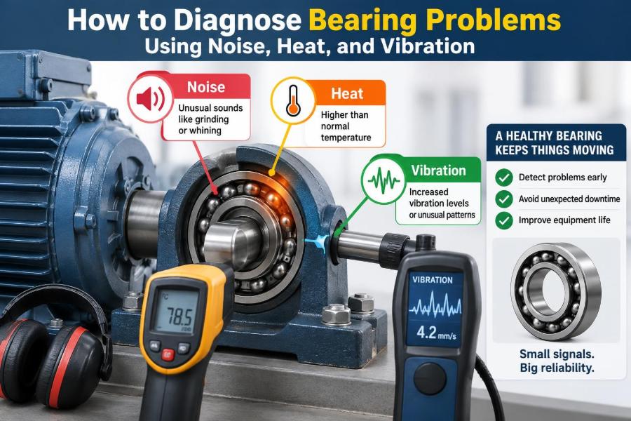

A motor that suddenly sounds rougher, a pump housing that feels unusually hot, or a fan that begins to shake can turn a routine shift into an urgent troubleshooting job. Often, the bearing is blamed first—and sometimes correctly. But the same symptoms can also come from poor alignment, imbalance, a loose foundation, belt problems, or process changes.
Bearings are small components with a large responsibility: they support rotating shafts while allowing controlled, low-friction motion. When their condition deteriorates, the machine may lose efficiency, consume more power, damage connected parts, or fail without much warning.
The most useful diagnosis does not rely on one symptom alone. It compares noise, temperature, vibration, operating history, and physical evidence, then asks whether the pattern makes mechanical sense.
This guide explains how to use those clues safely and systematically, whether you are learning condition monitoring or investigating a real machine on the plant floor.
🔩 What a Bearing Is Actually Telling You
A rolling-element bearing usually contains an inner ring, an outer ring, rolling elements such as balls or rollers, a cage that separates them, and lubricant. One ring commonly rotates with the shaft while the other is stationary in the housing.
In healthy operation, the rolling elements travel through lubricated contact zones. Small imperfections and normal vibration still exist, but they remain stable. A developing defect changes those contacts and creates repeatable mechanical impacts, friction, or motion errors.
Diagnosis is therefore an exercise in interpreting energy. Friction becomes heat, impacts become vibration, and vibration can become audible sound.
🧭 Start With a Baseline, Not a Hunch
A bearing temperature of 70°C may be concerning in one machine and normal in another. The useful question is often not “Is this value high?” but “Is this different from the machine’s normal operating condition?”
Record baseline measurements after installation and during known-good operation. Include load, speed, ambient temperature, lubricant type, measurement location, and instrument used. Trend data makes gradual deterioration visible before an absolute alarm limit is reached.
- Measure at comparable operating loads and speeds.
- Use the same sensor location whenever possible.
- Note process changes, such as thicker product, higher pressure, or altered belt tension.
- Compare identical machines only when their duty and installation are genuinely similar.
🛑 Make the Inspection Safe Before Making It Clever
Never place hands, clothing, probes, or improvised tools near exposed rotating equipment. A noisy bearing may be attached to a shaft, coupling, fan, or belt drive capable of causing severe injury.
Follow site procedures for guarding, lockout/tagout, electrical hazards, hot surfaces, and pressurized systems. Remote temperature sensors, permanently mounted vibration sensors, and approved listening tools reduce exposure, but they do not replace safe work practices.
If vibration rises rapidly, a housing becomes too hot to approach safely, or the machine rubs or binds, escalation is usually wiser than continued testing.
👂 Listen for a Change in Character
Sound is often the first clue because people notice a machine that “doesn’t sound right.” A healthy rolling bearing generally produces a smooth, steady broadband sound that blends into the machine’s normal operating noise.
A failing bearing may produce rumbling, growling, clicking, grinding, squealing, or a repeating tick. The description alone is not a diagnosis; for example, a dry belt can squeal, a damaged gear can growl, and a loose guard can rattle.
Listen for repeatability and location. Does the sound increase at the bearing housing? Does it appear only at a certain speed or load? Does it change after lubrication? Those observations are more valuable than a dramatic label such as “bad noise.”
🎧 Use Listening Tools With Realistic Expectations
An electronic stethoscope or contact probe can help isolate sound transmitted through a housing. Compare the suspect bearing with the matching bearing at the opposite end of the machine, or with a similar healthy unit.
Ultrasound instruments detect high-frequency energy beyond normal hearing and can be useful for early friction, lubrication, and impacting conditions. Their readings depend on probe position, sensitivity, machine speed, and background noise, so a single number should not be treated as a verdict.
Keep the contact point consistent and avoid touching thin guards, pipes, or resonant covers that may amplify unrelated noise.
🔊 Recognize Common Bearing Sound Patterns
Sound patterns provide leads, not certainty. The following comparisons can guide the next inspection step.
| Sound | Possible meaning | What else to check |
|---|---|---|
| Low rumble or growl | Rough raceway, contamination, or rolling-element damage | Vibration spectrum, lubricant debris, load condition |
| Sharp repeating click | Localized defect or looseness | Speed relationship, mounting fit, coupling condition |
| High-pitched squeal | Insufficient lubrication or another rubbing component | Belts, seals, brakes, contact points |
| Grinding | Severe surface damage, debris, or metal contact | Temperature, shutdown urgency, lubricant condition |
A sound that changes with shaft speed is especially useful. If it remains unchanged while speed changes, investigate stationary sources such as airflow, piping, electrical equipment, or structural resonance.
🌡️ Why Bearing Temperature Rises
Heat is generated when friction or lubricant shear increases. Common bearing-related causes include too little lubricant, too much lubricant, wrong viscosity, contamination, excessive preload, poor internal clearance, misalignment, and surface damage.
Temperature also reflects what the machine is doing. Higher load, speed, ambient temperature, process temperature, or nearby heat sources can raise the housing temperature without indicating bearing damage.
A bearing housing is not the bearing contact itself. The temperature measured outside the housing is delayed and influenced by heat flow through metal, airflow, and sensor contact quality.
🌡️ Measure Temperature in a Repeatable Way
An infrared thermometer is convenient, but shiny metal surfaces can produce misleading readings because emissivity—the ability of a surface to emit infrared energy—varies by finish and condition. A small patch of suitable high-emissivity tape or paint, where permitted, can improve consistency.
Contact probes and permanently installed resistance temperature detectors may provide more repeatable trends when mounted correctly. Whichever method is used, measure the same accessible point on the housing and allow the machine to reach a stable operating condition.
Compare both bearing locations. If the drive-end housing is consistently much hotter than the non-drive end under similar conditions, the difference deserves investigation.
📈 Focus on Temperature Trend and Rate of Change
A slow, stable temperature rise after startup may simply reflect the machine reaching thermal equilibrium. A continuing upward trend, however, suggests that generated heat exceeds the system’s ability to reject it.
A sudden increase can follow a lubrication error, loss of cooling, contamination event, load change, or beginning mechanical damage. Record the time, operating condition, and any maintenance action that preceded the change.
Do not assume that a cooler bearing is healthier. A bearing receiving too little lubricant may run cooler initially than one with an appropriate grease fill, until friction and damage begin to rise.
🧈 Understand the Lubrication Window
Grease or oil must form a film that separates contacting surfaces as much as operating conditions allow. With too little lubricant, metal contact, wear, and heat increase. With too much grease, rolling elements churn through excess lubricant, generating heat and possibly forcing grease past seals.
The right quantity, interval, and viscosity depend on bearing size, speed, load, orientation, sealing, and environment. A lubrication chart is not a suggestion; it is a starting point that should match the actual machine and lubricant.
Mixing incompatible grease thickeners can change consistency and oil release behavior. When a product change is necessary, follow the equipment and lubricant supplier’s compatibility guidance rather than assuming all greases mix safely.
💧 Inspect Lubricant as Evidence
Lubricant can reveal what is happening inside the bearing. Darkening alone is not proof of failure, but burnt odor, visible metallic particles, water, hardened grease, or unusual separation are meaningful warning signs.
For oil-lubricated systems, sample collection technique matters. A dirty bottle or sample taken from a stagnant drain point may tell you more about the container or sump than the bearing.
For grease-lubricated bearings, inspect purge material carefully when the design permits. Avoid opening sealed bearings merely to satisfy curiosity; unnecessary disturbance can introduce contamination.
📳 Vibration Is Motion With a Signature
Vibration analysis measures the motion produced by rotating and impacting components. It is especially useful because a bearing defect can create recognizable frequency patterns before noise becomes obvious or temperature rises significantly.
Acceleration is often useful for high-frequency bearing impacts, velocity for overall machine vibration, and displacement for relatively low-frequency shaft motion. None is universally “best”; the right measurement depends on the fault and machine.
The key is to distinguish a bearing-generated signal from vibration transmitted through the structure by another source.
📍 Place the Sensor Where the Forces Travel
Mount an accelerometer on a clean, rigid part of the bearing housing as close as practical to the load zone. A loose magnetic base, thick paint, flexible guard, or distant machine frame can distort high-frequency information.
Take measurements in consistent directions, commonly horizontal, vertical, and axial. Radial directions often reveal unbalance or looseness; axial vibration can be particularly informative for angular contact bearings, thrust-related issues, or coupling misalignment.
Document the point and direction. A vibration value without location, orientation, speed, and instrument settings has limited diagnostic value.
⚙️ Know the Difference Between Overall and Spectral Vibration
An overall vibration reading compresses a broad frequency range into one value. It is useful for screening and trending, but it may miss an early bearing defect whose high-frequency impacts contribute little to the total.
A spectrum separates vibration by frequency. It can reveal running speed, harmonics, gear mesh frequencies, electrical frequencies, and bearing-related activity. This makes it far more diagnostic, provided the analyst understands the machine’s kinematics.
A rising overall level deserves attention, but it does not automatically identify the bearing as the cause.
🧮 Learn the Bearing Defect Frequencies
Rolling bearings have characteristic frequencies associated with defects on the outer race, inner race, rolling elements, and cage. These are commonly abbreviated BPFO, BPFI, BSF, and FTF.
The exact values depend on bearing geometry: number of rolling elements, ball or roller diameter, pitch diameter, contact angle, and shaft speed. Bearing manufacturers often provide these values, while analysis software can calculate them when accurate geometry is available.
Because slip, load variation, and speed fluctuation exist, real signals may appear near rather than exactly at a calculated frequency. Sidebands and harmonics can provide useful context.
🧭 Interpret Outer-Race and Inner-Race Defects
An outer-race defect is stationary relative to the housing, so impacts often occur at a relatively stable position in the load zone. This can produce a clear pattern at the ball-pass frequency of the outer race and its harmonics.
An inner-race defect rotates with the shaft. The defect moves in and out of the load zone, so its vibration may be modulated by shaft rotation. In a spectrum, this can appear as characteristic frequency components with running-speed sidebands.
These are diagnostic tendencies, not rigid rules. Sensor location, load direction, speed stability, and signal processing all affect what appears in the data.
🔄 Watch for Rolling-Element and Cage Damage
Damage to a ball or roller can be more difficult to identify because the rolling element spins and travels around the bearing. The resulting ball-spin-frequency pattern may vary with slip and load.
Cage-related problems can produce low-frequency activity near the fundamental train frequency. A damaged cage is potentially serious because it controls rolling-element spacing; severe deterioration can quickly lead to secondary damage.
Do not diagnose a cage fault from one low-frequency peak alone. Looseness, belt effects, and structural vibration can occupy the same region.
📡 Use Envelope Analysis for Early Impacts
Envelope analysis, also called demodulation, is designed to expose repetitive high-frequency impacts from localized bearing defects. The impacts excite a structural resonance in the housing; the envelope process extracts the repeating impact rate.
This technique can detect small defects that are hidden in a conventional low-frequency spectrum. It works best when the sensor, frequency band, and machine condition are selected thoughtfully.
A poor mounting location or an unsuitable filter band can create confusing results. Treat envelope data as part of a measurement plan, not as an automatic fault detector.
⚖️ Separate Bearing Faults From Imbalance
Rotor imbalance commonly produces strong vibration at one times running speed, usually most visible in radial directions. The machine may run smoothly at low speed but shake increasingly as speed rises.
A bearing fault may coexist with imbalance, especially if repeated vibration loads damage the bearing over time. Replacing the bearing without correcting imbalance can shorten the replacement bearing’s life.
Look for the complete pattern: speed-frequency components, phase information when available, physical fan or rotor condition, and changes after cleaning or process buildup removal.
📐 Separate Bearing Faults From Misalignment
Coupling misalignment can create elevated axial vibration, running-speed harmonics, heat, seal wear, and bearing loading. It is a frequent reason a new bearing fails early despite being correctly installed.
Angular and offset misalignment are different geometries, and flexible couplings tolerate only limited misalignment. Thermal growth can also move machine shafts after alignment, which is why cold alignment targets may differ from running alignment.
Check soft foot before final alignment. A machine foot that bends the frame when tightened can distort alignment measurements and impose stress on the bearing housings.
🔧 Investigate Mechanical Looseness and Fits
Mechanical looseness can generate impacts, harmonics, and rattling that resemble bearing distress. Loose hold-down bolts, cracked bases, worn housings, loose bearing outer rings, or damaged shaft fits should all be considered.
A bearing ring should have the specified fit on the rotating or load-rotating component. A ring that creeps on its seat can fret the surface, create heat, and spread metal debris through the lubricant.
Inspect mounting hardware and structural condition during planned downtime. Tightening bolts blindly is not enough; damaged threads, distorted bases, and improper shimming require correction.
🧱 Consider the Machine’s Whole Force Path
A bearing does not operate in isolation. Belts can overload a shaft when tension is excessive. Pipe strain can pull a pump casing out of alignment. A fan with buildup can introduce cyclic load. A gearbox can transmit gear-related vibration into an adjacent bearing housing.
Trace forces from the driven equipment through the coupling, shaft, bearing, housing, base, and foundation. This systems view prevents the common mistake of treating a bearing as the root cause when it is actually the first component to show damage.
🧪 Inspect the Bearing After Removal
When removal is justified, preserve evidence. Mark orientation, record which side faced the load, and photograph the installation before cleaning parts. A bearing thrown into a scrap bin loses much of its diagnostic value.
Raceway discoloration, smearing, pitting, fluting, corrosion, cage damage, and polished creep marks each suggest different mechanisms. For example, electrical fluting often appears as washboard-like damage, while contamination commonly leaves dents or abrasive scoring.
Visual inspection should support—not replace—operating data. Some early fatigue damage is difficult to see without cleaning, magnification, or specialist examination.
⚡ Do Not Overlook Electrical Bearing Damage
Variable-frequency drives and certain electrical conditions can create shaft voltages that discharge through bearings. Repeated electrical discharge can damage raceways and lubricant, eventually producing fluting and distinctive high-frequency vibration.
Possible controls include proper grounding, shaft grounding devices, insulated bearings, or conductive paths designed for the equipment. Selection depends on the motor, drive system, and manufacturer guidance.
Replacing a fluted bearing without addressing the electrical path may only reset the failure cycle.
🌧️ Contamination and Corrosion Leave Clues
Dirt, water, chemical exposure, and poor storage can damage bearing surfaces long before obvious vibration develops. Hard particles indent raceways; moisture can corrode unprotected surfaces and degrade lubricant additives.
Frequent seal damage, washdown exposure, dusty air, or breathers that admit contaminated air should shift attention toward contamination control. Better sealing is helpful only if it suits shaft speed, runout, temperature, and the process environment.
Clean assembly practices matter just as much. A new bearing installed with debris on the shaft or in the housing begins life at a disadvantage.
🛠️ Follow a Practical Diagnostic Sequence
A repeatable sequence reduces guesswork and prevents one dramatic symptom from dominating the diagnosis.
- Confirm the machine’s operating condition, load, speed, and recent changes.
- Inspect externally for leaks, loose hardware, damaged guards, rubbing, and contamination.
- Listen safely and compare bearing locations.
- Measure housing temperatures at repeatable points.
- Collect vibration data in documented directions and locations.
- Compare results with baseline trends and bearing frequencies where available.
- Check alignment, balance, lubrication, fits, and force-path contributors.
- Decide whether to monitor, correct an external cause, plan replacement, or stop the machine.
The sequence can be scaled. A small utility fan may need only inspection and trending, while a critical compressor may justify advanced analysis and a formal risk review.
🗂️ Keep Records That Support Decisions
Useful records include bearing designation, installation date, lubricant, relubrication events, alignment values, vibration plots, temperature trends, operating speed, and photographs of removed parts. Include what changed, not merely what was measured.
Good records prevent repeated troubleshooting and help distinguish random damage from a recurring mechanism. They also make handovers stronger: the next technician can see whether a condition is stable, worsening, or linked to a previous intervention.
🚫 Avoid Common Diagnostic Traps
Several shortcuts produce confident but weak conclusions:
- Replacing the bearing first: this may hide the symptom while leaving misalignment, overload, or contamination unchanged.
- Adding grease until noise stops: excess grease can raise temperature and damage seals.
- Using one vibration reading as proof: trends, spectra, and operating conditions matter.
- Comparing unmatched machines: different loads and structures can produce different normal values.
- Ignoring installation practice: force applied through rolling elements during mounting can damage a new bearing immediately.
🚦Decide When to Monitor, Repair, or Stop
Not every indication requires an immediate shutdown. A stable, low-level vibration trend on a noncritical machine may be managed with increased monitoring and a planned repair. A rapidly rising temperature, severe roughness, visible grease burning, or major vibration increase calls for a more urgent response.
The decision should consider consequence as well as condition. A bearing in a small standby fan and one in a production-critical pump may show similar symptoms but require different risk controls.
When uncertainty is high, reduce risk by consulting experienced reliability personnel, the equipment manufacturer, or a qualified vibration analyst. Diagnosis should be honest about what the evidence can—and cannot—prove.
🧠 The Core Principle: Corroborate Every Clue
Noise tells you that energy is being radiated as sound. Heat suggests friction, lubricant shear, or load. Vibration shows how forces move through the machine. Each signal is valuable, but each has alternative explanations.
The strongest bearing diagnosis occurs when several clues agree: the housing grows hotter than its baseline, high-frequency vibration rises near expected defect frequencies, the sound localizes to the bearing, and inspection reveals a plausible lubrication, alignment, electrical, or contamination mechanism.
Diagnose the system that loads and supports the bearing, not just the bearing itself. That approach turns condition monitoring from symptom spotting into reliable problem solving.
When noise, heat, and vibration are interpreted together and compared with a sound baseline, bearing problems become clearer—and their root causes become much harder to miss. 🔧📈🛠️