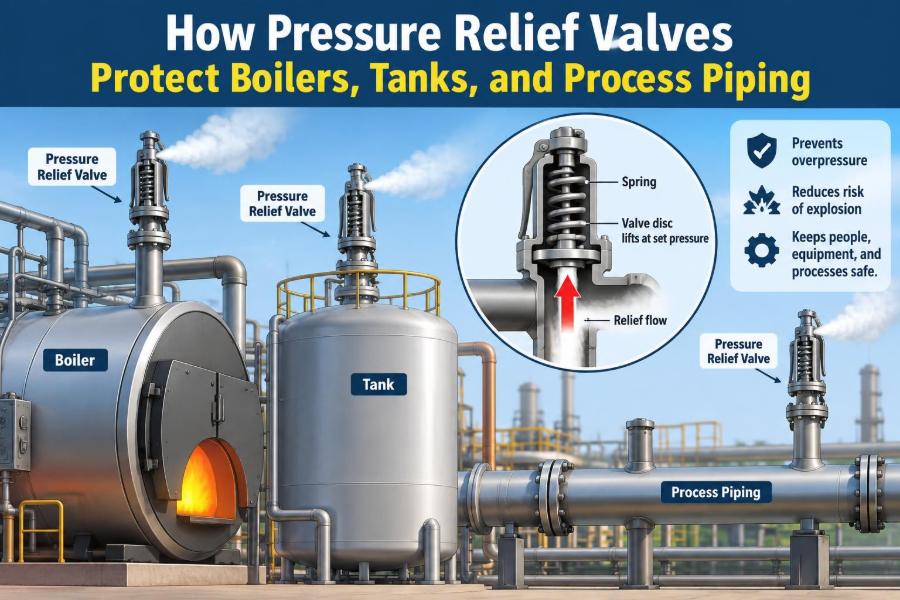

A boiler is warming up after maintenance. A control valve downstream is shut, steam demand is low, and heat is still entering the drum. Pressure begins to climb faster than the operator expects.
In another plant, a storage tank is being filled while its vent path is restricted. Elsewhere, a liquid-filled line sits between two closed block valves as the sun heats it. These are different systems, but they share one hazardous condition: pressure has no safe place to go.
Pressure relief valves are the final automatic barrier against that condition. They do not prevent every upset, and they are not a substitute for sound process control, but they can prevent equipment from being exposed to pressure beyond its safe limit.
For engineers, technicians, and operators, understanding how these devices work is essential. The correct valve must open at the correct pressure, pass enough fluid, discharge it safely, and reseat predictably when the upset ends. 🧯
⚠️ 1. The basic overpressure problem
Overpressure occurs when pressure inside equipment exceeds its permitted limit. If pressure continues to rise, a vessel, pipe, flange, gasket, tube, or fitting can deform, leak, rupture, or fail violently.
Pressure is created whenever a confined fluid is heated, compressed, generated, or blocked from expanding. A relief device creates a controlled escape route before the pressure reaches a damaging level.
The important idea is simple: the device does not eliminate energy. It safely releases enough mass, vapor, gas, or liquid to limit pressure during a credible upset.
🛡️ 2. A final layer, not the first control
Plants normally use several layers of protection. Basic controls regulate pressure during normal operation, alarms alert people to abnormal conditions, and shutdown systems stop or isolate a process when a limit is reached.
A pressure relief valve is generally an independent mechanical safeguard. It acts when earlier layers are unavailable, inadequate, bypassed, or too slow for the event.
This role explains why relief valves deserve careful engineering attention. A valve that is undersized, isolated, plugged, set incorrectly, or discharged into a hazardous location cannot provide the protection assumed in the design.
🔥 3. Common causes of excessive pressure
Different equipment faces different threats. The design basis for a relief valve begins by identifying realistic scenarios that could raise pressure beyond the allowable limit.
- Heat input to a blocked-in vessel, exchanger, or piping segment
- Blocked outlet while a pump, compressor, or upstream source continues operating
- External fire heating a vessel and vaporizing its contents
- Failure of a pressure-reducing valve or control valve
- Thermal expansion of trapped liquid
- Reverse flow, chemical reaction, or utility cross-contamination
- Tube rupture in a heat exchanger between high- and low-pressure sides
A credible scenario is not merely any imaginable failure. It must be evaluated using the process, equipment arrangement, operating modes, and applicable engineering requirements.
📏 4. Pressure terms engineers must separate
Several pressure terms sound similar but mean different things. Confusing them can lead to a relief system that is poorly selected or incorrectly documented.
| Term | Meaning in relief-system work |
|---|---|
| Design pressure | The pressure used to establish the mechanical design capability of equipment. |
| Maximum allowable working pressure | The maximum pressure permitted at a stated condition for the protected equipment. |
| Set pressure | The inlet pressure at which a relief device is adjusted to begin opening under specified test conditions. |
| Accumulation | The pressure increase above the allowable limit during discharge. |
| Overpressure | The pressure increase above set pressure while the device is relieving. |
| Backpressure | Pressure at the outlet of a relief device, which can affect its capacity and operation. |
Terminology can vary slightly by code, device type, and company practice. The engineering team must use definitions consistent with the governing design basis.
🌡️ 5. Why boilers need special attention
Boilers continuously add heat to water. If steam cannot leave at the required rate, energy keeps producing steam and pressure can rise quickly.
Boiler safety valves are therefore fundamental protective devices. Their sizing, installation, capacity, set pressure, discharge arrangement, testing, and maintenance are controlled by strict jurisdictional and code requirements.
A boiler valve must handle steam, not just pressure. Steam flow is compressible, hot, and capable of producing large reaction forces and hazardous discharge conditions. Never treat a boiler safety valve as a generic fitting.
🏭 6. Tanks can be pressurized in unexpected ways
Some tanks are designed for significant internal pressure, while others operate near atmospheric pressure and rely on vents. Both categories can be damaged if their pressure limits are exceeded.
A tank may become overpressured during filling, thermal expansion, inert-gas blanketing, vapor generation, blocked venting, or fire exposure. A low-pressure tank can also be vulnerable to vacuum if liquid is withdrawn or vapors condense without adequate air or gas admission.
Pressure and vacuum protection must be considered together when the tank can see both conditions. Protecting only the positive-pressure case leaves another possible failure mode open.
🧪 7. Process piping is also pressure equipment
Relief protection is often associated with vessels, but piping can be equally vulnerable. A small section of liquid piping blocked between valves can develop very high pressure from a modest temperature increase.
This is called thermal expansion of trapped liquid. Because liquids are only slightly compressible, expansion has little room to occur, so pressure rises sharply.
Small thermal relief valves are commonly used for these cases. Their required flow may be small, but their purpose is critical: they prevent a blocked liquid segment from becoming a pressure trap.
🔩 8. Safety valve, relief valve, and safety-relief valve
The names are often used loosely, but the operating behavior matters. A safety valve is commonly associated with compressible fluids such as steam or gas and typically opens rapidly with a noticeable pop action.
A relief valve is commonly associated with liquids and may open in proportion to the pressure increase above its set point. A safety-relief valve may be suitable for either service, depending on its certified design and application.
The name on a drawing is less important than confirming the valve’s approved service, capacity basis, materials, pressure rating, and behavior under actual process conditions.
🎯 9. What happens inside a spring-loaded valve
In a conventional spring-loaded valve, a spring holds a disc against a seat. Process pressure acts beneath the disc and creates an opening force.
As inlet pressure reaches the set pressure, the fluid force overcomes the spring force and the valve begins to lift. Valve geometry can amplify the opening force, allowing rapid lift and high discharge capacity in appropriate designs.
When pressure falls, spring force again becomes dominant and the disc closes. The pressure difference between opening and reseating is called blowdown.
🌀 10. Other relief-device designs
Spring-loaded valves are common, but they are not the only option. The right design depends on fluid properties, pressure level, backpressure, tightness needs, corrosiveness, and process consequences.
- Pilot-operated relief valves use process pressure and a pilot arrangement to control the main valve.
- Balanced bellows valves reduce the effect of variable outlet pressure on spring-loaded valve performance.
- Rupture disks open by bursting at a specified differential pressure and do not reseat.
- Pin devices use a structural element designed to fail at a defined load.
Non-reclosing devices require replacement after operation. Their simplicity can be valuable where rapid full opening, leak tightness, or isolation from corrosive fluid is important.
📌 11. Set pressure is not an arbitrary number
The set pressure is selected in relation to the protected equipment’s allowable pressure and the rules governing that equipment. It is not simply chosen below the normal operating pressure by a convenient margin.
Normal operating pressure must remain sufficiently below the set point to avoid simmering, leakage, chatter, or repeated lifting. At the same time, the set point must be low enough to protect the weakest relevant component.
When several devices protect one system, their set pressures and combined performance may need coordinated evaluation. This is especially important when staged relief is used.
📈 12. Capacity matters as much as opening pressure
A valve can open at the correct pressure and still be unsafe if it cannot pass enough flow. Required relieving capacity is the flow needed to prevent pressure from exceeding the allowed level during the governing scenario.
For example, a pump deadhead case may require relief of the pump’s flow at the relevant conditions. A fire case may require vapor generation to be estimated from heat input and wetted surface. A control-valve failure may require flow from an upstream supply.
Relief sizing is therefore a process calculation followed by a device selection task. It is not valid to select a valve only by matching pipe diameter.
💨 13. Fluid phase changes the calculation
Gas, vapor, steam, liquid, and two-phase mixtures do not behave alike during discharge. Compressible flow can reach a limiting velocity condition, while liquid flow depends strongly on density and pressure drop.
Flashing liquid creates vapor as pressure falls through the valve or downstream piping. Two-phase discharge can be difficult to predict and may need specialist methods, conservative assumptions, or dedicated analysis.
A valve rated for liquid service must not automatically be assumed adequate for vapor or flashing service. The relieving fluid and its state at the valve inlet must be identified clearly.
🧱 14. Inlet piping can defeat a good valve
The connection between protected equipment and relief valve should be short, direct, and properly sized. Restriction in this path creates pressure loss while the valve is flowing.
Excessive inlet pressure drop can make a spring-loaded valve unstable. It may chatter, cycle, fail to achieve full lift, or suffer seat and internals damage.
Good layout minimizes bends, long runs, reducers, and unnecessary fittings. The inlet line must also avoid pockets where liquid, solids, or condensate can collect and impair operation.
🚧 15. Outlet piping creates backpressure
After the valve opens, fluid enters the discharge path. Friction, elevation, headers, silencers, scrubbers, condensate, and other operating relief devices can create backpressure.
Backpressure may be constant or may build only while the valve is discharging. Conventional spring-loaded valves can be sensitive to variable built-up backpressure, which can alter opening behavior and capacity.
The discharge system must be assessed as part of the relief system, not as an afterthought. A correctly sized valve attached to a restrictive outlet may not perform as intended.
🌬️ 16. Discharge must go somewhere safe
Relief flow may be hot, toxic, flammable, corrosive, noisy, oxygen-deficient, or high velocity. Directing it onto a walkway, near an air intake, or close to ignition sources can turn successful pressure protection into another hazard.
Possible destinations include a safe elevated vent, a closed flare or disposal system, a recovery system, a quench arrangement, or another engineered containment route. The selection depends on the fluid and the facility’s hazard analysis.
Discharge piping needs support because relief flow can create large thrust loads. Its outlet must also be designed to prevent rain entry, freezing, blockage, and hazardous liquid accumulation.
🧭 17. Installation orientation and accessibility
Many spring-loaded relief valves are intended for vertical installation with the spindle upright. This orientation helps the moving parts operate as designed and reduces the risk of binding or uneven loading.
The valve should be accessible for inspection, testing, removal, and replacement without exposing workers to unnecessary hazards. Its identification tag must remain readable, and its outlet must remain visible enough to detect leakage where appropriate.
Installation instructions from the manufacturer and governing requirements always take priority. A valve’s orientation, support needs, and drainage details are part of its functional design.
🔒 18. Isolation valves require strict control
An isolation valve between protected equipment and its relief valve can accidentally remove the only pressure-protection path. For this reason, such valves are often prohibited or tightly controlled by applicable rules and site procedures.
Where isolation is permitted for maintenance, the arrangement must ensure that required protection remains available. This may involve locked-open valves, car seals, administrative controls, or changeover arrangements with more than one relief device.
Never close or block a relief-valve inlet simply to stop a leak or make maintenance easier. Escalate the condition and follow the approved plant procedure.
🧯 19. Rupture disks and relief valves together
A rupture disk may be installed upstream of a relief valve to isolate the valve from corrosive, fouling, polymerizing, or toxic process fluid. It can also improve seat tightness in services where minor leakage is unacceptable.
However, the combination introduces design questions. The space between the disk and valve can become pressurized if the disk leaks, potentially affecting valve performance. Disk opening characteristics and pressure loss must also be considered.
A rupture disk downstream of a valve may protect the discharge system or isolate it from corrosive conditions, but it can create backpressure concerns. Combined devices must be evaluated as a system.
🔍 20. Inspection finds hidden degradation
Relief valves often sit quietly for years, so degradation can remain invisible until the moment they are needed. Corrosion, deposits, damaged seats, weakened springs, plugged drains, and incorrect assembly can all affect performance.
Inspection programs commonly consider process severity, service history, device type, prior test results, corrosion risk, and applicable requirements. A fixed calendar interval alone may not capture every relevant risk.
External checks can reveal leaking outlets, missing seals, damaged discharge piping, unauthorized isolation, vibration, or an obscured nameplate. These observations are valuable because they identify problems before a demand occurs.
🧰 21. Testing and calibration confirm performance
Testing verifies that a device opens at the intended set pressure and that its internal parts are in acceptable condition. Depending on the valve and service, testing may occur in a workshop, on a test bench, or through carefully controlled in-place methods.
Calibration must account for the conditions specified for the device. Temperature, backpressure, test medium, and installation effects can influence the observed result.
After maintenance, documentation should record the valve identification, set pressure, work performed, parts replaced, test outcome, seal status, and return-to-service date. Traceability supports both safety and future troubleshooting.
🧼 22. Fouling, freezing, and corrosion are design issues
In dirty or reactive service, the small clearances inside a valve can become blocked or sticky. A valve may then open late, fail to reseat, leak, or remain shut when pressure rises.
Cold weather introduces another hazard. Condensed water in discharge piping can freeze, creating a blockage; viscous fluids can also become difficult to drain or move.
Material selection, heat tracing where appropriate, drainage, insulation, flushing connections, protective coatings, and service-specific valve designs can reduce these risks. Maintenance cannot fully compensate for a poor service match.
🧠 23. Human factors can compromise protection
Many relief-system failures begin with ordinary human actions: a blind installed for maintenance and not removed, a valve left shut, an altered set pressure, an undocumented process change, or a discharge line used as a convenient support point.
Clear tags, locked positions, line-up checklists, permit controls, accurate drawings, and independent verification reduce the chance that a protective device is unknowingly defeated.
Training should explain the consequence behind each rule. People are more likely to respect a lock-open requirement when they understand it preserves a life-safety pressure path.
🗺️ 24. Process changes demand a new review
A relief valve is sized for defined conditions, not for every future version of a plant. Increasing pump capacity, changing feed composition, raising utility pressure, modifying control logic, or adding insulation can change the required relieving load.
Even changes that appear small can affect the scenario basis. A new upstream source might raise blocked-outlet flow, while a different chemical may change vapor pressure, density, corrosion behavior, or two-phase flashing characteristics.
A formal management-of-change review should determine whether the existing device, inlet, discharge header, and disposal system remain adequate. Relief protection is a living part of process design.
🧾 25. Relief documentation connects the whole system
A useful relief-device record contains more than a tag number. It connects process assumptions, equipment limits, valve data, installation details, inspection history, and discharge destination.
📋 Key information to maintain
- Protected equipment and governing pressure limit
- Relief scenario, required capacity, and relieving conditions
- Valve type, size, materials, certified capacity, and set pressure
- Inlet and outlet piping details, including backpressure assumptions
- Discharge destination and associated hazards
- Test, repair, and inspection records
Accurate records make it possible to review a device years later without rebuilding the entire engineering basis from memory.
👷 26. What operators should notice in the field
Operators are often the first people to see conditions that affect relief protection. A lifting valve, a leaking outlet, unusual noise, frost, corrosion, or a changed valve lineup deserves attention.
Repeated lifting is not normal proof that a valve is working. It may indicate unstable control, excessive operating pressure, a blocked downstream path, thermal expansion, or a valve that is not reseating correctly.
Operators should report abnormal conditions promptly and follow site procedures for response. They should never cap, plug, lift, gag, adjust, or isolate a relief device unless specifically authorized under a controlled procedure.
✅ 27. The core principle: protect the pressure boundary
Pressure relief valves protect boilers, tanks, and piping by limiting pressure before the equipment’s pressure boundary is overloaded. Their effectiveness depends on the complete chain: correct scenario identification, sound sizing, proper valve selection, low-loss inlet piping, acceptable backpressure, safe discharge, and disciplined maintenance.
A relief valve is not simply a component with a set pressure stamped on its nameplate. It is part of a carefully engineered system that must work under the abnormal conditions everyone hopes never occur.
The core principle is this: provide a reliable, adequately sized, unobstructed path for excess pressure to be relieved safely before the pressure boundary fails. 🧯⚙️✅