
Centrifugal pumps are among the most widely used machines for moving liquids. They are found in water-supply networks, power plants, chemical factories, refineries, ships, irrigation systems, HVAC installations, wastewater plants, and industrial processing facilities. 🚰🏭
At first glance, a centrifugal pump seems simple: an electric motor spins a wheel inside a casing, and liquid flows from one place to another. But the actual process involves a carefully coordinated transformation of energy.
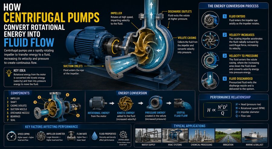
The pump receives mechanical rotational energy from a motor or other driver. A rotating component called an impeller transfers this energy to the liquid. The liquid gains velocity and pressure, and the pump casing then helps convert part of that velocity into useful pressure that pushes the fluid through piping.
In simple terms:
Motor Rotation → Impeller Rotation → Fluid Velocity → Pressure Increase → Fluid Flow
⚙️➡️🌀➡️💧➡️📈
This energy-conversion process is what makes centrifugal pumps so effective for continuously moving large volumes of liquid.
⚙️ What Is a Centrifugal Pump?
A centrifugal pump is a type of dynamic pump.
Unlike positive-displacement pumps, which trap a fixed amount of liquid and physically force it forward, centrifugal pumps add energy continuously to flowing liquid using a rotating impeller.
The main components usually include:
- impeller,
- pump casing,
- suction inlet,
- discharge outlet,
- shaft,
- bearings,
- mechanical seal or packing,
- driver such as an electric motor.
The impeller is the heart of the pump.
It typically consists of curved blades, or vanes, arranged around a central hub.
When the motor rotates the shaft, the impeller spins with it.
The rotating vanes interact with the liquid and transfer mechanical energy into the fluid. 🌀
💧 How Liquid Enters the Pump
Fluid usually enters a centrifugal pump through the suction pipe.
It travels toward the center of the impeller, called the eye.
The eye is located near the rotational axis of the impeller.
At this point, fluid velocity may still be relatively moderate.
As the impeller spins, its blades capture and accelerate the liquid outward.
This movement from the center toward the edge of the impeller is one of the defining characteristics of centrifugal pumping.
🌀 Why the Impeller Pushes Fluid Outward
When the impeller rotates, the liquid inside it is forced to move along curved blade passages.
The blades continuously transfer angular momentum to the fluid.
The liquid gains:
- velocity,
- kinetic energy,
- pressure energy.
As the fluid travels from the impeller eye toward the outer diameter, its tangential speed increases because the outer portion of the impeller moves faster than the inner portion.
The blade tip speed is related to:
u = ωr
where:
- u = tangential speed,
- ω = angular rotational speed,
- r = radius from the center.
This means liquid near the outer edge can receive much more energy than liquid near the center. ⚡
📈 How Rotation Becomes Pressure
The impeller does not simply “throw” liquid into the pipe.
Its primary role is to increase the fluid’s mechanical energy.
Part of that energy appears as increased velocity.
The pump casing then helps convert some of this kinetic energy into static pressure.
This is extremely important because piping systems often require pressure to overcome:
- elevation differences,
- pipe friction,
- valves,
- heat exchangers,
- filters,
- process equipment.
Without sufficient pressure, the liquid would not continue flowing through the system.
🐌 The Volute Casing
Many centrifugal pumps use a spiral-shaped casing called a volute.
The volute begins narrow near the impeller and gradually becomes wider as it wraps around the pump.
Fluid exits the impeller at high velocity and enters the volute.
As the flow area becomes larger, fluid velocity can decrease.
Through this controlled deceleration, part of the kinetic energy is converted into pressure energy.
Conceptually:
High velocity + lower pressure → Lower velocity + higher pressure
This energy conversion follows fluid-dynamic principles related to conservation of energy. 📐
🧩 Diffuser-Type Pumps
Some centrifugal pumps use a diffuser instead of, or in addition to, a volute.
A diffuser contains stationary vanes surrounding the impeller.
These vanes guide the high-speed liquid into gradually expanding passages.
As the passages expand, fluid velocity decreases and pressure rises.
Diffuser designs are common in certain:
- multistage pumps,
- vertical turbine pumps,
- high-pressure pumps.
The basic principle is similar to the volute: recover velocity energy and turn it into useful pressure.
🧠 Bernoulli’s Principle and Pump Energy
Fluid flow is often analyzed using Bernoulli-type energy relationships.
A flowing liquid can possess several forms of mechanical energy:
- pressure energy,
- kinetic energy,
- gravitational potential energy.
A pump adds energy to the system.
A simplified energy relationship may be written as:
Pump energy added = increase in pressure + change in velocity + change in elevation + losses
In practical systems, some of the pump’s energy is used to overcome pipe friction and equipment resistance.
The remainder creates the required flow and pressure.
🏗️ What Is Pump Head?
Pump performance is often described using head rather than pressure.
Head represents the amount of mechanical energy the pump adds per unit weight of fluid.
It is usually expressed in units of length, such as:
- meters,
- feet.
For example, a pump with a head of 30 meters can theoretically support a column of the pumped liquid approximately 30 meters high, ignoring losses and system details.
Pressure and head are related through:
Pressure = density × gravity × head
This is why the same pump head can correspond to different pressures for liquids of different densities. 📏
📊 Flow Rate and Head Are Connected
A centrifugal pump does not produce one fixed flow rate.
Its operating flow depends on the resistance of the piping system.
At low flow, the pump may produce relatively high head.
As flow increases, the available head generally decreases.
Manufacturers represent this relationship using a pump performance curve.
A typical pump curve shows:
- flow rate on the horizontal axis,
- head on the vertical axis.
The actual operating point occurs where the pump curve intersects the system resistance curve. 🎯
🔄 What Is the System Curve?
The piping system also has its own hydraulic behavior.
As flow increases, friction losses increase.
For many systems, friction loss rises approximately with the square of flow rate.
The system may require pressure to overcome:
- static elevation,
- pipe friction,
- fittings,
- control valves.
A system curve represents the head required at different flow rates.
The point where:
Pump Head = System Head
determines the actual operating flow.
This is why simply selecting a “large pump” does not guarantee the desired flow.
The pump and system must be matched correctly.
🏆 Best Efficiency Point
Every centrifugal pump has an operating region where it performs most efficiently.
This is called the Best Efficiency Point, or BEP.
At the BEP:
- hydraulic losses are relatively low,
- flow through the impeller is well aligned,
- vibration is usually minimized,
- energy efficiency is high.
Operating too far away from the BEP can cause:
- increased vibration,
- recirculation,
- bearing loads,
- seal wear,
- reduced efficiency.
Engineers therefore try to select pumps that operate near their preferred range during normal service. ⚙️✅
⚡ Pump Power
The hydraulic power delivered to a fluid can be approximated as:
Hydraulic Power = ρgQH
where:
- ρ = fluid density,
- g = gravitational acceleration,
- Q = volumetric flow rate,
- H = pump head.
The motor must supply more power than this because no real pump is perfectly efficient.
If pump efficiency is η, then required shaft power is approximately:
Shaft Power = Hydraulic Power / η
This shows why efficiency matters.
A low-efficiency pump wastes more electrical energy as heat, turbulence, and mechanical losses. 💡
🔌 Electric Motors Commonly Drive Pumps
Most industrial centrifugal pumps are powered by electric motors.
The motor converts electrical energy into rotational mechanical energy.
The complete energy chain becomes:
Electrical Energy → Motor Rotation → Shaft Power → Impeller Energy → Fluid Pressure and Flow
Each stage has some energy loss.
Engineers therefore consider both:
- motor efficiency,
- pump efficiency.
A well-selected high-efficiency pump and motor can significantly reduce operating costs over years of service.
🌀 Why Priming Is Necessary
Many centrifugal pumps cannot pump air effectively.
Before starting, the pump casing and suction line may need to be filled with liquid.
This process is called priming.
If a conventional centrifugal pump starts while full of air, the impeller may simply spin without generating enough pressure difference to draw liquid into the pump.
Priming ensures that the impeller can immediately transfer energy to liquid.
Some pumps are designed to be self-priming, but ordinary centrifugal pumps often require the casing to remain flooded. 💧
⚠️ What Is Cavitation?
One of the most important problems in centrifugal pumps is cavitation.
Cavitation occurs when local liquid pressure drops below the liquid’s vapor pressure.
Tiny vapor bubbles form.
As these bubbles move into higher-pressure regions, they collapse violently.
This collapse can create microscopic shock waves that damage metal surfaces.
Symptoms may include:
- rattling or gravel-like noise,
- vibration,
- reduced flow,
- reduced head,
- impeller damage.
Over time, cavitation can pit and erode the impeller. ⚠️🌀
📉 Why Pressure Drops at the Suction
The lowest pressure in a centrifugal pump often occurs near the impeller eye.
If suction pressure becomes too low, cavitation risk increases.
This can happen because of:
- excessive suction lift,
- long suction piping,
- clogged strainers,
- high fluid temperature,
- insufficient tank level,
- undersized suction pipes.
Good suction-system design is therefore essential.
📏 What Is NPSH?
Engineers evaluate cavitation risk using Net Positive Suction Head, abbreviated NPSH.
Two values are important:
NPSH Available (NPSHa)
The suction head actually available from the system.
NPSH Required (NPSHr)
The minimum suction head required by the pump to avoid unacceptable cavitation under specified conditions.
For reliable operation:
NPSHa should exceed NPSHr with suitable margin.
This is one of the most important checks in centrifugal pump selection.
🧱 Types of Impellers
Centrifugal pump impellers come in several designs.
🔒 Closed Impeller
A closed impeller has vanes enclosed between side plates.
It is efficient and commonly used for clean liquids.
🔓 Open Impeller
An open impeller has exposed vanes.
It can handle fluids containing larger solids more easily.
🌓 Semi-Open Impeller
A semi-open impeller uses one side plate.
It provides a compromise between efficiency and solids-handling ability.
The correct impeller depends on the fluid and application.
🌊 Single-Stage Pumps
A single-stage centrifugal pump uses one impeller.
It is suitable for many ordinary applications involving moderate head.
Examples include:
- water transfer,
- cooling systems,
- irrigation,
- general industrial circulation.
Single-stage pumps are simple, reliable, and relatively easy to maintain.
🏢 Multistage Pumps
When higher pressure is required, several impellers can be arranged in series.
This creates a multistage centrifugal pump.
The discharge of one impeller feeds the next.
Each stage adds additional head.
Conceptually:
Stage 1 → +Head
Stage 2 → +More Head
Stage 3 → +Even More Head
Multistage pumps are used in applications such as:
- boiler feedwater,
- high-rise building water supply,
- reverse-osmosis systems,
- high-pressure industrial services.
🧭 Radial, Mixed, and Axial Flow Pumps
Centrifugal-type dynamic pumps can be categorized according to how fluid moves through the impeller.
➡️ Radial Flow
Fluid exits mainly perpendicular to the shaft.
These pumps are well suited to producing relatively high head.
↗️ Mixed Flow
Fluid exits in both radial and axial directions.
These pumps provide a balance of head and flow.
⬆️ Axial Flow
Fluid moves primarily parallel to the shaft.
Axial-flow pumps are designed for very high flow at relatively low head.
They resemble propellers and are often used for drainage and large-scale water movement.
🚰 Where Centrifugal Pumps Are Used
Centrifugal pumps are extremely versatile.
They are used in:
🏙️ Municipal Water Systems
To move drinking water through treatment plants and distribution networks.
🌾 Irrigation
To transport water from rivers, wells, or reservoirs to agricultural fields.
🏭 Chemical Processing
To circulate process fluids between reactors, tanks, and heat exchangers.
🚢 Marine Systems
Ships use centrifugal pumps for cooling water, ballast, bilge handling, and many auxiliary systems.
❄️ HVAC
Chilled-water and cooling-water systems rely heavily on centrifugal pumps.
🔥 Power Plants
Pumps move cooling water, condensate, boiler feedwater, and other process fluids.
🔩 Shaft and Bearings
The impeller is connected to a rotating shaft.
The shaft transfers mechanical torque from the motor to the impeller.
Bearings support the shaft and keep it aligned.
Poor bearing condition can cause:
- vibration,
- misalignment,
- seal damage,
- increased friction.
Bearing lubrication and condition monitoring are therefore important maintenance tasks.
💧 Mechanical Seals Prevent Leakage
Where the rotating shaft passes through the stationary pump casing, liquid could leak outward.
A mechanical seal helps prevent this.
Mechanical seals use precisely finished sealing surfaces pressed together.
One surface rotates with the shaft while another remains stationary.
A very thin fluid film provides lubrication between them.
Seal failure can cause:
- leakage,
- process contamination,
- safety hazards.
In some applications, traditional packing is used instead.
📉 Pump Efficiency Losses
Not all shaft power reaches the fluid.
Losses occur through several mechanisms.
🌊 Hydraulic Losses
Turbulence, recirculation, and friction inside the impeller and casing consume energy.
🔩 Mechanical Losses
Bearings and seals create friction.
💧 Leakage Losses
Some fluid may leak internally from high-pressure regions back toward low-pressure regions.
Efficient pump design tries to minimize all of these losses.
🔄 Recirculation Inside the Pump
When a pump operates far below its intended flow rate, flow can become unstable.
Some liquid may circulate internally instead of moving smoothly through the pump.
This is called internal recirculation.
It can cause:
- vibration,
- heating,
- noise,
- hydraulic damage.
This is another reason centrifugal pumps should not normally operate far outside their recommended range for long periods.
🚫 What Is Deadheading?
If the discharge valve of a centrifugal pump is completely closed while the pump continues running, the condition is called deadheading.
Flow becomes nearly zero.
The pump may still transfer energy into the trapped liquid.
That energy becomes heat.
If the condition continues, the liquid can become very hot and damage:
- seals,
- bearings,
- pump internals.
Industrial systems may use minimum-flow lines or protection logic to prevent dangerous deadheading.
🎛️ Controlling Pump Flow
There are several ways to control centrifugal pump output.
🚪 Throttling Valve
A discharge valve can be partially closed to increase system resistance and reduce flow.
This is simple but wastes energy because the valve deliberately creates pressure loss.
⚡ Variable Frequency Drive
A Variable Frequency Drive, or VFD, changes motor speed.
Reducing pump speed can reduce flow and head more efficiently.
VFDs are widely used in modern pumping systems where demand changes over time.
📐 Pump Affinity Laws
For geometrically similar conditions, centrifugal pump performance changes predictably with speed.
Approximate affinity laws state:
Flow ∝ Speed
Head ∝ Speed²
Power ∝ Speed³
This means even a modest reduction in speed can significantly reduce power consumption.
For example, lowering speed by 20% can reduce required power by much more than 20% under suitable conditions.
This is why variable-speed pumping can save substantial energy. 💡
🔄 Pumps in Parallel
Two pumps can be connected in parallel.
Both pump into the same discharge system.
Parallel operation is mainly used to increase flow capacity.
For example:
Pump A + Pump B → Higher Combined Flow
This arrangement is useful when system demand varies significantly.
One pump can operate during low demand, and another can start when demand increases.
📈 Pumps in Series
Pumps can also be connected in series.
The discharge from one pump enters the suction of the next.
This mainly increases total head.
Conceptually:
Pump 1 Head + Pump 2 Head = Greater Total Head
Series arrangements may be useful where high system pressure is required.
🔧 Maintenance and Condition Monitoring
Centrifugal pumps can operate for years, but they require maintenance.
Engineers monitor:
- vibration,
- bearing temperature,
- seal leakage,
- motor current,
- suction pressure,
- discharge pressure,
- flow rate.
Changes in these values can indicate developing problems.
For example:
Increasing vibration → Possible imbalance or bearing wear
Reduced discharge pressure → Possible impeller wear or blockage
Higher motor current → Possible excessive load
Predictive maintenance can identify issues before catastrophic failure occurs.
🧠 Why Centrifugal Pumps Are So Popular
Centrifugal pumps dominate many liquid-handling applications because they provide several advantages:
- continuous smooth flow,
- relatively simple construction,
- few moving parts,
- high flow capacity,
- easy motor coupling,
- good reliability,
- broad range of sizes.
They are especially effective for low- to moderate-viscosity liquids.
For extremely thick fluids or applications requiring very precise displacement, another pump type may be more appropriate.
🏭 The Energy Conversion Inside a Centrifugal Pump
The operation of a centrifugal pump can be summarized as a chain of energy transformations.
First, an electric motor or other driver rotates the shaft. ⚙️
The shaft spins the impeller.
The impeller transfers angular momentum to the liquid, increasing its velocity and mechanical energy.
The high-speed liquid leaves the impeller and enters the volute or diffuser.
These stationary passages slow the liquid in a controlled way and convert part of its velocity energy into pressure.
That pressure then drives the fluid through pipes, valves, heat exchangers, tanks, and other equipment. 💧➡️🏭
The central engineering principle is:
A centrifugal pump converts rotational mechanical energy into fluid flow by using a spinning impeller to accelerate liquid and a casing or diffuser to convert part of that velocity into useful pressure. 🌀⚙️➡️💧📈
This simple but powerful mechanism is why centrifugal pumps quietly move enormous volumes of water, chemicals, cooling fluids, and process liquids throughout modern infrastructure every day.