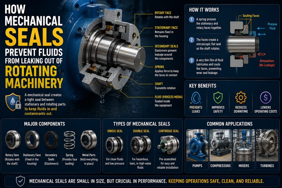

Rotating machines such as pumps, mixers, compressors, and agitators often contain liquids or gases under pressure while a shaft passes through the machine housing and spins at high speed. That creates a difficult engineering problem: how can the shaft rotate freely without allowing the process fluid to leak out around it? 💧🔄
One of the most important solutions is the mechanical seal.
A mechanical seal creates a controlled sealing interface between a rotating shaft and a stationary housing. Instead of trying to eliminate all movement at the shaft penetration, the seal uses two extremely flat faces that slide against each other while maintaining a very thin lubricating film between them.
The basic idea is:
Rotating shaft ➡️ Rotating seal face 🔄 ➡️ Microscopic fluid film 💧 ➡️ Stationary seal face ➡️ Machine housing
When designed and operated correctly, this arrangement allows the shaft to rotate while keeping leakage extremely small.
Mechanical seals are found throughout industry in equipment handling water, oil, fuels, chemicals, refrigerants, food products, pharmaceuticals, and many other fluids. 🏭
🔍 Why Rotating Shafts Are Difficult to Seal
Imagine a centrifugal pump moving water through a pipeline.
Inside the pump, an impeller spins rapidly.
The impeller is attached to a shaft that extends through the pump casing to an electric motor.
The pump casing contains pressurized liquid, but the shaft must pass through the casing wall.
If there were simply an open gap around the shaft, liquid would leak through it.
A stationary gasket cannot solve the problem because the shaft must rotate.
Engineers therefore need a seal that can accommodate continuous motion.
Historically, many machines used packing, which consists of rings of compressible material squeezed around the shaft.
Packing can work well, but it usually allows some controlled leakage and creates friction.
Mechanical seals can often provide much lower leakage and reduced shaft wear.
🧩 The Main Parts of a Mechanical Seal
Although mechanical seal designs vary widely, many contain the same basic components:
- 🔄 Rotating seal face
- 🧱 Stationary seal face
- 🌀 Spring or bellows
- ⭕ Secondary seals such as O-rings
- 🔩 Metal hardware
- 🛡️ Gland or seal housing
The two seal faces are the heart of the system.
One face rotates with the shaft.
The other remains stationary.
These faces are pressed together while the shaft spins.
🪞 The Seal Faces Are Extremely Flat
Mechanical seal faces are manufactured to extraordinary flatness.
Common face materials may include:
- Carbon
- Silicon carbide
- Tungsten carbide
- Ceramics
The surfaces are polished so precisely that only a microscopic gap exists between them during operation.
Why is this important?
If the faces were rough or uneven, fluid could easily flow through gaps.
Instead, highly polished surfaces create an extremely restricted leakage path.
At the same time, the faces cannot simply be forced together with unlimited pressure because excessive contact would generate heat and wear.
The seal must therefore maintain a carefully controlled balance.
💧 The Microscopic Fluid Film
Perhaps the most surprising feature of a mechanical seal is that the two faces are not always intended to operate in completely dry contact.
A microscopic film of process fluid often exists between them.
This film performs several important functions:
- Reduces friction
- Removes heat
- Lubricates the faces
- Prevents rapid wear
The film may be only a few micrometers thick.
A tiny amount of fluid can cross the seal faces during operation, but the leakage is generally extremely small compared with an open shaft gap or traditional packing.
So a mechanical seal does not necessarily mean literally zero molecular leakage.
Instead, it controls leakage to a very low level.
⚖️ How the Faces Stay Together
The seal faces must remain in contact despite:
- Shaft rotation
- Pressure changes
- Vibration
- Thermal expansion
- Small shaft movements
A combination of forces keeps them together.
These commonly include:
🌀 Spring Force
Springs push one seal face toward the other.
This helps establish contact when the machine is stopped or pressure is low.
💧 Hydraulic Force
Process pressure can also push the faces together depending on seal geometry.
🔄 Hydrodynamic Effects
The microscopic fluid film can generate forces that slightly separate the faces during operation.
The final operating position results from a balance between closing and opening forces.
This equilibrium is one of the most important principles in mechanical seal design.
🌀 Why Springs Are Necessary
Suppose the pump is switched off.
There is little or no hydraulic pressure inside the seal chamber.
Without another source of force, the two faces might separate and allow leakage.
Springs maintain contact even when the machine is not running.
Common spring arrangements include:
- Multiple small springs
- Single coil springs
- Metal bellows
Once the machine starts, fluid pressure and hydrodynamic forces also contribute to the face loading.
⭕ Secondary Seals Stop Leakage Around the Faces
The polished faces prevent leakage along the rotating interface, but fluid could potentially escape around other components.
Secondary seals prevent this.
Common secondary seals include:
- O-rings
- Elastomer bellows
- PTFE wedges
- Gaskets
For example, an O-ring may prevent fluid from leaking between the stationary seal ring and its housing.
Another O-ring may seal between a rotating component and the shaft.
These secondary seals usually move only slightly compared with the main rotating faces.
🔄 Rotating Face vs. Stationary Face
In a typical arrangement, one seal ring is attached to the shaft and rotates with it.
The other is fixed to the pump casing.
Conceptually:
Motor → Shaft → Rotating Seal Face
                     ||
                 Fluid Film
                     ||
              Stationary Face → Pump Housing
The rotating face may spin thousands of times per minute while the stationary face remains fixed.
The precision interface between them provides the primary seal.
🧱 Why Carbon Is Commonly Used
Carbon is widely used as a mechanical seal face material because it offers useful properties such as:
- Low friction
- Good self-lubricating characteristics
- Resistance to many chemicals
- Ability to run against harder surfaces
A common face combination is:
Carbon vs. silicon carbide
The carbon provides favorable sliding behavior, while silicon carbide provides hardness, wear resistance, and good thermal conductivity.
Other combinations are selected depending on fluid chemistry, temperature, pressure, and abrasiveness.
💎 Silicon Carbide and Tungsten Carbide
For demanding applications, harder materials may be required.
💎 Silicon Carbide
Silicon carbide offers:
- Excellent hardness
- Strong chemical resistance
- Good thermal conductivity
- High wear resistance
It is widely used in corrosive and abrasive services.
🔩 Tungsten Carbide
Tungsten carbide is extremely strong and wear resistant.
It is often used where mechanical toughness is important.
Material selection is critical because incompatible face materials can wear rapidly or react with the process fluid.
🌡️ Heat Is One of the Biggest Challenges
Even with a thin lubricating film, friction exists between the seal faces.
This generates heat.
If heat is not removed, the faces can overheat.
Excessive temperature may cause:
- Fluid vaporization
- Elastomer damage
- Face distortion
- Cracking
- Accelerated wear
The fluid surrounding the seal often carries heat away.
This is one reason pumps should not normally operate dry unless the seal is specifically designed for it.
🚫 Why Dry Running Can Destroy a Seal
Imagine a water pump starts with no liquid inside the seal chamber.
The faces begin sliding without their normal fluid film.
Friction increases sharply.
Within a short time, the faces can become extremely hot.
Possible consequences include:
- Carbon face damage
- Thermal cracking
- Distortion
- O-ring failure
Dry running is therefore a common cause of mechanical seal failure.
Correct priming and startup procedures are important.
🌬️ Vaporization Between the Faces
Even when liquid is present, the seal can fail if the fluid starts boiling between the faces.
This can happen when:
- Temperature is too high
- Pressure is too low
- Frictional heat is excessive
- The fluid is highly volatile
Vapor provides much poorer lubrication than liquid.
The seal faces may then experience unstable contact and rapid wear.
Engineers therefore control seal-chamber pressure and temperature carefully.
⚙️ Balanced vs. Unbalanced Mechanical Seals
Mechanical seals can be classified as balanced or unbalanced.
The difference relates to how process pressure acts on the seal face geometry.
⚖️ Balanced Seal
A balanced seal reduces the effective hydraulic closing force on the seal faces.
This can:
- Reduce friction
- Lower heat generation
- Improve high-pressure capability
- Extend seal life
🔧 Unbalanced Seal
An unbalanced seal may have stronger closing forces.
It can be simpler and suitable for lower-pressure applications.
The correct design depends on operating conditions.
🧮 Why Too Much Closing Force Is Bad
It might seem logical that pushing the faces together harder would always reduce leakage.
But excessive face pressure increases friction.
More friction produces more heat.
More heat damages lubrication.
The result can actually be a shorter seal life.
Mechanical seal design is therefore a balancing problem:
Enough force to control leakage ✅
but:
Not so much force that friction becomes destructive ❌
🌊 Seal Flush Systems
Some pumps use a seal flush to improve mechanical seal conditions.
A small stream of liquid may be directed toward the seal chamber.
The flush can:
- Remove heat
- Wash away solids
- Prevent deposits
- Maintain suitable pressure
- Improve lubrication
The flushing liquid may come from the pump discharge or from an external clean source.
Engineers choose the arrangement based on the process fluid.
🏭 API Seal Plans
In petroleum, chemical, and process industries, mechanical seal support systems are often organized according to standardized piping arrangements commonly known as API seal plans.
These systems may provide:
- Flushing
- Cooling
- Barrier fluids
- Buffer fluids
- Pressure control
- Leakage monitoring
The objective is to create a controlled environment around the seal.
For hazardous fluids, the support system can be just as important as the seal itself.
🛡️ Single Mechanical Seals
A single mechanical seal uses one primary pair of seal faces.
It is common in applications where very small leakage to the environment is acceptable and the fluid is not exceptionally hazardous.
A simple pump handling clean water may use a single seal.
However, more demanding processes may require multiple sealing stages.
🔐 Double Mechanical Seals
A double mechanical seal uses two sets of seal faces.
A separate fluid is maintained between them.
This intermediate fluid may be called a:
- Barrier fluid
- Buffer fluid
depending on pressure arrangement.
The structure may be conceptually represented as:
Process fluid ➡️ Inner seal ➡️ Barrier/buffer fluid ➡️ Outer seal ➡️ Atmosphere
This arrangement provides additional protection against hazardous or valuable process fluids escaping.
🧪 Barrier Fluid Systems
In a pressurized double seal, the barrier fluid is maintained at a pressure above the process pressure.
If leakage occurs across the inner seal, clean barrier fluid tends to leak inward toward the process rather than hazardous process fluid leaking outward.
This can be extremely important when handling:
- Toxic chemicals
- Flammable hydrocarbons
- Environmentally dangerous fluids
The barrier fluid also lubricates and cools the seal faces.
🌫️ Gas Seals
Not every mechanical seal uses liquid lubrication.
Some high-speed compressors use dry gas seals.
These seals use specially designed grooves that generate a thin gas film between the rotating faces.
The faces operate with extremely small separation.
Dry gas seals can minimize friction and leakage in high-speed compressor applications.
They are common in equipment handling natural gas and other process gases.
🔬 Hydrodynamic Grooves
Some advanced seal faces contain microscopic engineered grooves.
As one face rotates, these grooves help generate pressure in the fluid film.
That pressure can lift the faces slightly apart.
This creates non-contacting or lightly contacting operation.
Reducing direct face contact can greatly lower wear.
The exact groove geometry is carefully engineered using fluid dynamics and tribology.
📐 Shaft Alignment Matters
Mechanical seals tolerate small shaft movements, but excessive misalignment can cause problems.
If the shaft is bent or poorly aligned, the rotating face may wobble.
This can create uneven contact.
Consequences may include:
- Uneven wear
- Excessive leakage
- Vibration
- Face cracking
Proper alignment between the pump and motor is therefore essential.
🌀 Shaft Runout
Shaft runout describes how much the rotating shaft deviates from perfect circular rotation.
Even tiny amounts can affect a mechanical seal.
High-quality rotating equipment is manufactured and aligned to keep runout within acceptable limits.
Dial indicators and other precision instruments may be used during maintenance to measure it.
📳 Vibration Can Damage Seals
Pumps experiencing strong vibration can dramatically shorten seal life.
Common causes include:
- Bearing damage
- Misalignment
- Cavitation
- Unbalanced rotating components
- Pipe strain
Vibration causes repeated movement at the seal faces and secondary seals.
A leaking seal may therefore be a symptom of a larger machine problem rather than the original cause.
💥 Cavitation and Seal Reliability
Cavitation occurs when local pressure inside a pump falls low enough for vapor bubbles to form.
When these bubbles collapse, they create vibration and damaging pressure pulses.
Cavitation can harm:
- Impellers
- Bearings
- Mechanical seals
A pump operating under poor suction conditions may therefore experience repeated seal failures even if the seal itself is correctly selected.
🧹 Solids and Abrasive Fluids
Mechanical seals can struggle when fluids contain sand, crystals, or other abrasive particles.
Particles may enter the face interface and cause wear.
Special seal designs may use:
- Harder face materials
- Clean flushing systems
- Cyclone separators
- External barrier fluids
The goal is to prevent abrasive contaminants from damaging the sealing surfaces.
❄️ Crystallizing and Sticky Fluids
Some process liquids crystallize when they cool or contact air.
Others form sticky deposits.
These materials can build up around the mechanical seal and prevent the spring-loaded components from moving freely.
Engineers may use:
- Heating
- Flushing
- Quenching
- Specialized seal geometry
to keep the seal environment clean.
🧪 Chemical Compatibility Is Essential
Every seal component must be compatible with the process fluid.
A chemical may attack an elastomer O-ring even if the seal faces themselves are resistant.
Engineers therefore evaluate compatibility for:
- Face materials
- Elastomers
- Springs
- Metal components
Temperature can also change chemical compatibility.
Choosing the wrong O-ring material can cause swelling, hardening, cracking, or rapid leakage.
📉 What Does a Mechanical Seal Failure Look Like?
Signs of a failing mechanical seal may include:
- Visible leakage
- Dripping near the shaft
- Vapor emissions
- Unusual noise
- Rising seal temperature
- Contaminated barrier fluid
- Frequent loss of seal pressure
A small amount of leakage may be normal for some designs, but sudden or increasing leakage requires investigation.
🔧 Common Causes of Mechanical Seal Failure
Mechanical seals often fail because of operating conditions rather than manufacturing defects.
Common causes include:
- Dry running
- Misalignment
- Excessive vibration
- Incorrect installation
- Dirty fluid
- High temperature
- Cavitation
- Wrong seal material
- Improper flush conditions
- Excessive shaft movement
Understanding the root cause is essential.
Simply installing another identical seal may lead to another failure.
🧰 Installation Requires Precision
Mechanical seal faces are precision components.
During installation, technicians must avoid:
- Scratching the faces
- Touching polished surfaces with dirty hands
- Incorrect spring compression
- Damaging O-rings
- Misaligning components
Even a tiny scratch across a seal face can create a leakage path.
Cleanliness during assembly is therefore critical.
📏 Face Flatness and Lapping
Seal faces are often finished through a process called lapping.
Lapping uses extremely fine abrasives to create surfaces with exceptional flatness.
The flatness may be measured using optical techniques.
Such precision ensures that when the two faces meet, the leakage path remains microscopic.
This manufacturing accuracy is one reason mechanical seals can control high-pressure fluids with surprisingly small components.
🏭 Where Mechanical Seals Are Used
Mechanical seals appear in countless industries.
🛢️ Oil and Gas
Used in pumps and compressors handling hydrocarbons.
⚗️ Chemical Processing
Used where corrosive or hazardous fluids must be contained.
🚰 Water Treatment
Used in clean-water and wastewater pumps.
🍺 Food and Beverage
Sanitary seal designs help prevent contamination.
💊 Pharmaceutical Manufacturing
High-purity seals are used where cleanliness is critical.
🚢 Marine Systems
Mechanical seals are used in pumps and some shaft applications aboard ships.
Their widespread use reflects how fundamental the rotating-shaft sealing problem is.
🧠 A Simple Example: Centrifugal Pump Seal Operation
Imagine a centrifugal pump moving chemical process liquid.
The sequence is:
- ⚙️ The motor rotates the pump shaft.
- 🔄 The seal’s rotating face spins with the shaft.
- 🧱 The stationary face remains fixed.
- 💧 A microscopic liquid film forms between the faces.
- 🌀 Springs and hydraulic pressure maintain appropriate face loading.
- 🌡️ The fluid film lubricates and removes heat.
- ⭕ Secondary seals prevent leakage around the seal components.
- ✅ Process liquid remains largely contained inside the pump.
This occurs continuously while the machine may be rotating thousands of times per minute.
🌟 The Bigger Picture
Mechanical seals prevent fluids from escaping rotating machinery by solving an unusual engineering challenge: creating a reliable boundary between a moving shaft and a stationary housing.
Their effectiveness comes from a carefully controlled interface between two extraordinarily flat surfaces.
The complete sealing system can be summarized as:
Process fluid 💧 ➡️ Polished seal faces 🪞 ➡️ Microscopic lubricating film ➡️ Controlled face pressure ⚖️ ➡️ Extremely low leakage ✅
Springs maintain contact, hydraulic pressure influences face loading, secondary seals stop leakage around other paths, and specialized support systems control temperature, pressure, cleanliness, and lubrication.
The result is a component that can contain pressurized fluids while a shaft rotates thousands of times every minute.
Mechanical seals demonstrate an important engineering principle: successful sealing does not always mean eliminating movement. Instead, engineers create a precisely controlled moving interface where friction, lubrication, pressure, heat, and material properties remain in balance.
When that balance is maintained, pumps, mixers, compressors, and other rotating machines can operate for long periods while losing only an extremely small amount of the fluid they are designed to contain. ⚙️💧🔒