There are many methods that have been used to produce aluminum and aluminum alloy powders including gas and centrifugal atomization, ultrasonic or pulsed atomization, melt spinning with attrition, and mechanically alloying. Gas atomization is used for several applications.
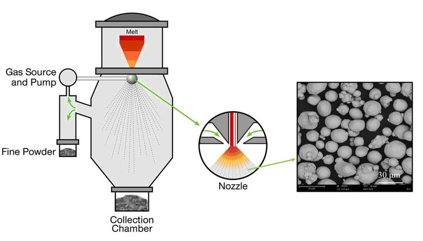
In gas atomization, a high-velocity gas jet disintegrates molten aluminum into droplets that solidify to form the powder. In the Alcoa process (Fig. 1), the material flow during atomization is vertically upward (also known as “updraught”). Molten metal of the appropriate composition is supplied from a holding or melting furnace at the required temperature to the atomizing bay. The liquid is drawn from the bay through a liquid delivery tube into the atomizing nozzle. This is achieved by the aspirating effect (suction) caused at the nozzle end of the delivery tube by the flow of the high-pressure atomizing gas in the nozzle. When the liquid metal meets the high-velocity gas, it is broken up into droplets and sprayed as a jet. The droplets are quenched by the gaseous atmosphere in the chamber to solidify as powder particles. These particles, together with a substantial volume of cooling air, are then drawn through a chiller chamber into the collection system consisting of two sets of cyclones. After the cyclones, the powder is transported in an atmosphere of inert gas to the screens and pack-outs where they are packed under inert gas into drums and bins or onto railroad cars or trucks.

Fig. 1 Schematic of the Alcoa process for atomizing aluminum powder. Entire operation is under computer control. Powder is packed in drums or bins or is loaded for bulk shipment in trucks or railroad cars.
Because aluminum powder forms an explosive mixture with air over a wide range of metal-to-air ratios, aluminum powder plants have explosion hazards associated with them. The Alcoa process (Fig. 1) incorporates several safety features. The bottom of the chiller chamber is closed rather than open to prevent ingress of combustible dust and foreign matter into the atomizing zone. Cooling air entering the chiller chamber is filtered in order to remove foreign matter and ignition sources, such as rust particles. The chiller chamber walls are reinforced. Explosion vents are located in the chiller chamber, along the exhaust duct, and in other critical locations, such as the lids of the cyclone abatement chambers. These vents open up and minimize pressure buildup in the event of an explosion. To reduce explosion hazards between the atomizing nozzle and the cyclones, the airborne concentration of aluminum powder is kept to a level below which forms an explosive mixture (lower explosive limit, LEL). Airflow in the system is created by means of an eductor, so that powder does not have to travel through a rotating fan, which eliminates a significant static electricity ignition source. The whole plant is built in stainless steel and fully grounded to eliminate the danger of sparking and static buildup. The transport of powder after the cyclones is done in an atmosphere of inert gas, as noted above, to substantially reduce the explosion hazard. A certain level of oxygen is maintained in the inert gas atmosphere to ensure that the powder does not become pyrophoric.
Workers are removed entirely from areas containing the greatest hazards by substitution of computerized controls, remote TV surveillance, and automated operations. Conductive shoes are provided to workers in powder handling areas. Good housekeeping and training of operators are essential elements of safe operation in an aluminum powder plant. Regular audits of plant equipment and operating practices are carried out to ensure compliance. Areas of improvement identified in such audits and by risk assessment procedures are implemented on a timely basis.
The industry has recognized the hazards of aluminum powder. Manufacturers and users of aluminum powders cooperate in reporting and analyzing incidents through the auspices of The Aluminum Association. The Association holds safety workshops and supports research relating to safety funded by the members.
Control of particulate emissions in industrial plants is an important criterion. In the United States, these requirements vary from state to state. Pennsylvania has one of the strictest specifications limiting particulate emissions rate to 0.09 g/Nm3 (0.04 grains/ft3) of dry process air for aluminum powder plants. To meet these stringent requirements, manufacturers of aluminum powders often collect the powder in two stages of cycloning followed by a baghouse. Opacity of the plume from the plant is monitored and recorded. The upper limit for opacity is often specified at 10% max. These two specifications of emissions do not in general correspond to each other for aluminum powder plants (Fig. 2). This may be attributed to fine particles (<1 /’m) causing a disproportionately high obscuration of the sunlight in the plume than coarser particles would cause.
12.0
di c
1 80
12.0
| Q | |||||||
| O | o | ■—o” | |||||
| i | |||||||
| 0 | O | ||||||
| 0 / | oO o | , Texas A Boar<J lin | ir ift | ||||
0 0.020 0.040 0.060 0.030 0.100 0.120 0.140 0.160
Dust concentrations, grains/s
0 0.020 0.040 0.060 0.030 0.100 0.120 0.140 0.160
Dust concentrations, grains/s
Fig. 2 Dust concentration and mean opacity readings measured in a pilot aluminum atomizer
Vertically upward aspirating processes, such as that operated by Alcoa, permit better control of the metal delivery rate to the nozzle and thus the production of the widest range of powder grades: fine, medium, and coarse. Aluminum powder atomizing can be accomplished also by directing the molten metal stream either horizontally or vertically downward. Systems that utilize metal-head pressure to induce molten metal flow through the nozzle often atomize either vertically downward or horizontally. Aspirating systems, on the other hand, usually prefer to atomize horizontally or vertically upward. Multiple nozzles are often used in commercial operation to achieve the required rates of production.
Atomizing Nozzle Technology. The first nozzle used for atomizing aluminum powders was invented by Hall in the late 1920s (Ref 4). In the Hall design, the atomizing gas (compressed air) is delivered through an annular orifice around the nozzle at a converging angle, as shown in Fig. 3. The gas flow creates a suction (aspiration) effect at the tip of the nozzle that is utilized to draw the molten metal into the nozzle. The amount of gas delivered by the nozzle is controlled by the size of the air gap, and pressure and temperature of the gas. Rate of metal flow and resultant powder particle size are influenced by the aspirating force, the nozzle metal orifice diameter, and the vertical distance between the nozzle and the molten metal level.

Fig. 3 Aspirating nozzle design developed by E.J. Hall in 1920s. Source: Ref 4
The Hall nozzle is a good example of the general class of confined nozzles, or close-coupled nozzles. This nozzle design aims to contact the liquid metal with the gas at or close to the gas jet exit plane, thus making use of the high jet velocities at that point. It leads to efficient breakup of the liquid, resulting in finer powders, and is the preferred method for aluminum and rapidly solidified fine powders of other metals. It can be operated vertically upwards or downwards or in the horizontal position. Careful design of the nozzle is required, however, to avoid the quenching of the metal by the gas jet, which can lead to premature solidification at the nozzle tip.
In the operation of the confined design nozzles, it has been observed that the molten metal presents itself as a thin film to the gas jet. This filming effect, which is beneficial for efficient breakup of the liquid, occurs from the gas flow pattern and toroidal recirculation vortexes above the nozzle (Fig. 4). The vortexes in this flow pattern cause the liquid to spread radially on the top of the delivery tube into a thin film. This is the preferred operating regime for producing fine powders. When the metal flow rate is too high, the filming effect is partially lost, and some of the metal is pulled into the low-velocity wake and does not film effectively (Ref 5, 6). Such operation leads to coarser powders and to the formation of undesirable flakes in the powder.

Fig. 4 Fluid flow pattern at the tip of a confined nozzle during atomization
The toroidal recirculation vortexes of confined nozzles are caused by fluid entrainment on the inner boundaries of the annular jet (Ref 7). When a jet exits from an annular nozzle, a mixing zone is formed due to the shearing action of the jet on the surrounding fluid. As there is no supply of fluid in the central region to satisfy the entrainment requirements of the inside boundaries, the jet is forced to draw this fluid from the mainstream jet itself. By forming recirculation vortexes, the jet is able to feed itself with its own fluid and hence satisfy entrainment requirements. Associated with the vortexes is a zone of subatmospheric pressure at the tip of the nozzle, and the resulting radial pressure forces draw in the annular jet toward the axis. As the converging streamlines approach the axis, a region of stagnation is set up at some distance downstream from the axis. The high pressure at this point redirects the flow away from the axis, until finally the combined jet expands in the same way as a single round jet. Similar recirculation flows can also form on the outside due to entrainment on the outer boundary if the amount of fluid available is restricted, as in the case of a jet being blown into a closed container. It is important to avoid recirculating flows in the vicinity of the atomizing jets that can lead to multiple collisions between the spray and the powder particles and result in excessive satelliting.
The low pressure (suction, aspiration) created at the nozzle tip is a useful feature of the confined design. It is employed to draw the liquid metal into the nozzle from the crucible in updraught operation, as mentioned above. Additionally, the presence of suction at the point of contact between the gas and the liquid avoids the potentially hazardous blowback effects observed in free fall nozzles for certain jet geometries. The level of suction created by a nozzle is found to be extremely sensitive to nozzle geometry, atomizing gas, and operating pressure (Ref 8).
Nozzle designs used in the aluminum powder industry are proprietary and information on their performance is not available. Information has become available in recent years on several different confined nozzle designs developed for use with molten metals, some of which have been applied to aluminum. It is instructive to review some of the more important designs.
Ultrasonic gas atomization (USGA) has been promoted by Grant (Ref 9). This nozzle invented by Kohlswa Jernwerk of Sweden and patented in the United States in 1961 uses a modification of the original design with a multitude of discrete holes for gas delivery. Each gas jet contains a pair of resonating (Hartmann) cavities in its path, as indicated in Fig. 5. The original patent claims that ultrasonic vibrations are created in the gas jet that lead to the production of finer powders. Published reports of experimental work with metal powders have not supported that claim. Further, the modified design has been shown to lead to unnecessarily high frictional losses (Ref 12).

Fig. 5 Schematic of USGA nozzle design. Source: Ref 10
Gas jets
Fig. 5 Schematic of USGA nozzle design. Source: Ref 10
NIST Design. The nozzle developed at NIST is similar to the USGA design, but it does not contain the Hartmann cavities (Ref 13, 14). The gas jets are inclined to metal delivery axis at an included angle of 45 °C (Fig. 6). With such designs, too, under certain conditions, positive pressure rather than suction is created at the tip of the nozzle. The selection of operating conditions then becomes crucial. Recent work by Mates (Ref 6, 16) has shown that filming of the molten metal takes place also in this design. It is, however, sensitive to the operating parameters and is not always complete, and metal can exit the nozzle in the form of ligaments and sheet (Fig. 6) as proposed by NIST workers.

Fig. 6 Particle formation mechanism proposed for the NIST nozzle that operates vertically downwards. Source: Ref 15
Nanoval Nozzle Design. Nanoval has recently introduced a nozzle design (Fig. 7) in which the molten metal is delivered to the throat of a converging-diverging nozzle in the form of a thin stream (Ref 10). It is thus conceptually similar to the free fall design; but because the metal stream is always kept very thin and it is delivered directly to the throat of the nozzle, this design is capable of producing very fine powders. Nanoval has produced stainless steel powders of 6 /’m median diameter by this method in pilot quantities. No filming is likely to occur in this design, because it is necessarily restricted to very low rates of production and best suited possibly for precious metals. The manufacturer also claims substantial gas savings.

Fig. 7 Schematic of Nanoval nozzle design. Source: Ref 11
Free fall nozzle designs (Fig. 8) are also known to be used in the aluminum powder industry. In this design, the liquid metal issues in the form of a stream from a tundish and falls 50 to 200 mm by gravity. Then it is atomized by the gas directed at a point, either by means of discrete jets or an annular nozzle concentric with the metal stream. This method is easy to operate but highly inefficient and is not suitable for making fine powders.

Free fall
Fig. 8 Atomization design characteristics: Ot, angle formed by free falling molten metal and impinging gas; A, distance between molten metal and gas nozzle
Formation of Powder Particles. Recent studies on the operation of confined nozzles have shown that the liquid film obtained in these nozzles breaks up in two stages to form the powder particles. The first stage (primary breakup) occurs at the point of first contact between the liquid film and the gas jet along the edge of the delivery (Fig. 4). Liquid droplets formed at this stage can have up to 500 /Jm diameter under normal operating conditions with aluminum. These droplets undergo further disintegration in flight (secondary breakup), as is evident from the absence of such large particles in the resulting powders. Similar stages are described for the NIST design by Ridder et al. (Ref 13) for the breakup ligaments and the droplets formed.
Primary breakup is not well understood, but it is known from experiments that unsuitable nozzle designs or operating conditions can lead to incomplete breakup and/or formation of filaments at the nozzle tip, which may eventually become flakes in the powder. It is accepted that proper completion of the primary breakup stage is essential for the production of fine powders. The filming mechanism facilitates the breakup. Also, swirl in the atomizing gas is likely to be helpful. Indeed, swirl is one of the important features of the nozzle design patented by Hall in 1928 for making metal powders. Most interestingly, Miller (Ref 11) has recently introduced nonaxisymmetric metal delivery tubes and has found them to be beneficial in the atomization of superalloys. He reported that they lead to the formation of multiple plumes at the tip of the nozzle, which would break the ligaments into smaller parts and thus enhance the efficiency of the primary breakup stage. Miller also notes that with asymmetric nozzles, the pinching of the plume is much reduced. He suggests that the resulting reduction in the level of droplet collision and coalescence would also contribute to the improved efficiency observed. It is important to note that the largest benefits were observed at the higher range of atomization rates (lower range of the gas/metal ratios) that correspond to coarse powders.
Secondary Breakup. The breakup of single droplets in a flowing gas has been studied using materials that are liquid at room temperature, such as water, oils, and glycerin. Lane (Ref 15), one of the earliest to publish work in the field, identified two main mechanisms of breakup as “bag” mechanism and “stripping” mechanism, shown in Fig. 9 applicable at low and high Weber numbers (W), respectively.

Fig. 9 Secondary breakup mechanisms proposed by Lane. Source: Ref 17
Experimental evidence for the occurrence of secondary breakup in metal powder production can be obtained from studies of the atomizing spray at very low metal flow rates. At such low rates, individual droplets become visible (Fig. 10) and show “tails” in the direction of the gas flow as suggested by Lane. Weber numbers obtained in metal atomization are generally very high, and Unal (Ref 7) concluded on that basis that breakup occurs by stripping. In that mode, the droplet first deforms in such a way as to present a convex surface to the gas flow. The edges of this saucer-shaped droplet are then drawn out into a thin sheet and torn into ligaments, which are later broken into smaller droplets. These particles (daughter particles) form the fine size range of the powder. As droplets get progressively smaller through disintegration, a point comes at which surface tension forces, which are inversely proportional to diameter (4 /d), become sufficiently great to resist the aerodynamic drag forces responsible for the breakup. At this point, secondary breakup ceases, and the droplets solidify to form the coarse range of powder particles. From earlier studies of the breakup of single droplets, Unal (Ref 7) deduced that this occurs when the Weber number (W) takes on a value of 13. That is, for stable particles:

Fig. 10 Metal film left in the tip of the nozzle in the rundown mode
A range of stable particle sizes is obtained because the gas decelerates and the particles accelerate as a function of distance from the nozzle. The lower limit for stable sizes is that obtained at the tip when the relative velocity is a maximum. This has been estimated at 30 /’m for aluminum and for the common atomizing gases, such as nitrogen, argon, and helium. The largest size found in the powder can be used to estimate the relative velocity at which secondary disintegration is complete. These estimates have indicated that the process is likely to be completed while the gas flow is still supersonic in a well designed nozzle.
It is important to appreciate that the presence of stable particles in the final product can apply only to such liquids as molten metals, which have high surface tension and low viscosity. For other liquids with low surface tension, the stable sizes may be so small as to be comparable to that of the daughter particles, in which case they would be indistinguishable. Unal et al. (Ref 19) found that to be true with wax powders atomized in air. These powders have a tighter size distribution represented by the Rosin-Ramler law as opposed to the log-normal law that generally applies to atomized metal powders.