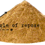
Both internal and external friction values are important when characterizing the flow properties of a metal powder. Internal friction is caused by solid particles flowing against each other and is expressed by the angle of internal friction and the effective angle of internal friction. Both can be determined during the course of measuring cohesive strength with a Jenike shear cell (Fig. 5), as described in Ref 5.
External friction is expressed as the wall friction angle or coefficient of sliding friction. The lower the coefficient of sliding friction, the less steep the hopper walls need to be for powder to flow along them (mass flow). Also, the easier a feed shoe indexes to and from a die, the more uniform the flow of powder into the die cavity.
The coefficient of sliding friction can be measured by sliding a sample of powder across a stationary wall surface using a shear tester. The arrangement of the cell is shown in Fig. 10. In this case, a coupon of the wall material is placed on a filler so that the top surface of the coupon is the horizontal plane of the force measuring stem. The ring and packing mold are placed over the wall material coupon and filled with the powder.
Applied weighl
Applied weighl
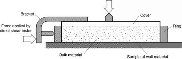
Fig. 10 Shear cell used in measuring wall friction properties. Test setup design allows shear stress (see horizontal arrow) to be measured as a result of applied weights (see vertical downward arrow).
After scraping off the excess material level with the top of the mold, a twisting top is placed over the powder. A vertical force is applied to the top by means of a weight hanger. This force causes a vertical pressure <7t in the material. By means of a special wrench, a number of oscillating twists is now applied to the cover. This preconsolidates the powder and ensures a uniform specimen.
The twisting load is taken off, the twisting top and the mold are removed, the excess material is scraped off level with the top of the ring, and the test cover is placed on the material. A smaller load is now placed on the cover, and the stem of the shearing device is advanced against the bracket (Fig. 10). All the tests necessary to determine the coefficient of sliding friction are now run without replacing the powder.
Before the start of a test, the ring is twisted and manually lifted slightly off the wall material coupon to prevent it from dragging on the wall coupon. Several (say, six) one or two pound weights are placed directly on top of the cover of the shear cell to give the largest required normal stress Cfw. The stem is advanced. When the shear stress 7~w has leveled off, one weight is removed, after a while Tw again levels off, another weight is removed and so on, until all the weights have been removed. The cover, ring, and the enclosed powder are then weighed. Their weight plus the superimposed weights determine the normal stresses ffw.
A typical recorder chart is shown in Fig. 11. The points (Cfw, Tw) are plotted in Fig. 12. A smooth line drawn through these points is the wall yield locus, WYL. Typically, the WYL is convex upward.
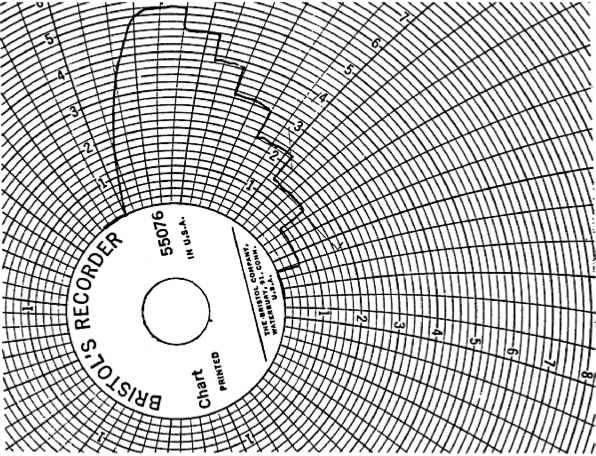
Fig. 11 Typical recorder chart in measurement of <P’ (wall friction angle)
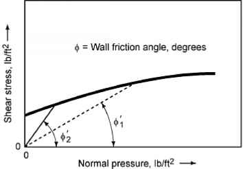
Fig. 12 Typical results of the test setup shown in Fig. 10 to help engineers determine wall friction angle ($’)
The coefficient of sliding friction is the ratio of the shear force required to cause sliding to the load applied perpendicular to the wall material coupon. The arc tangent of this value is the wall friction angle (Ref 3, 4).
The following variables can affect the internal and external friction values of a metal powder and are similar to those affecting cohesiveness:
• Pressure: Typically, as consolidating pressure increases, the effective angle of internal friction decreases. Similarly, the coefficient of sliding friction often decreases as pressure acting normal to the plate increases. However, the internal angle of friction is an intrinsic characteristic of the material that may increase, decrease, or remain the same as pressure acting on the material increases.
• Moisture content: As moisture increases, many bulk solids become more frictional.
• Particle size and shape: Typically, fine materials and those with a wide range of particle sizes are somewhat more frictional than coarse materials or those with a narrow particle size distribution; so the flow of the former is often more troublesome. Shape plays a role in that angular particles tend to interlock and also dig into a wall surface, thereby creating more friction.
• Temperature: For many materials, higher temperatures can cause particles to become more frictional.
• Time of storage at rest: If allowed to adhere to a wall surface, many powders experience an increase in friction between the particles and the wall surface. Such situations require steeper bin walls for unaided flow.
• Wall surface: The initial condition of a surface can play a major role in how materials slide along it. Smoother surfaces are typically less frictional, although this is not always true. Also, as a carbon steel container ages, corrosion can roughen the walls, making sliding more difficult.
Friction data are used to:
• Design a mass flow hopper: Values of both wall friction angle and effective angle of internal friction are required to design a mass flow hopper. Using these angles along with design charts given by Jenike (Ref 3), one can determine allowable hopper angles required to promote mass flow.
• Anticipate sliding on chutes: A chute is used to transfer material from one point to another in a bulk handling system. By definition, the cross section of a chute is only partially full at any given time, and the discharge rate of a powder is equal to the chute filling rate.
Beyond the impact point, the acceleration of a particle on a chute is directly related to the difference between the wall friction angle of the material and the chute angle. As long as the chute is steeper than the wall friction angle, particles will continue to accelerate. Otherwise they will slow down and may eventually block the chute.