A stepper motor drive is a circuit which is used to drive or run a stepper motor. It is often called a stepper motor driver. A stepper motor drive usually consists of a controller, a driver and the connections to the motor.A lot of drive circuits are available in the market today. Many circuits are so easy to interface to a motor that you can almost instantly connect the stepper motor to it and you are ready to run the motor. These circuits come in a variety of ratings for current and voltage and one should select them according to the needs of the motor which will be used.
Essential Components of Stepper Motor Drive
1. Controller(Essentially a micontroller or a microprocessor)
2. A driver IC to handle the motor current
3. A power supply unit
1. Switches, Potentiometers
2. Heat sink
3. Connecting wires
Controller of Stepper Motor Drive
Selection of a controller is the first step to building a driver. It must have a minimum of 4 output pins for the stepper. Apart from this, additionally it must contain timers, ADC, serial port etc. depending on the application in which the driver will be used.
Driver
Nowadays, people are moving away from discrete driver components like transistors to more compact integrated IC’s. These driver IC’s are available at reasonable costs and are easier to implement in terms of assembling which improves the overall design time of the circuit. The drivers must be selected to suit the motor ratings in terms of current and voltages. ULN2003 series of drivers are most popular in non H Bridge based application and this is apt for a stepper motor drive. Each Darlington pair inside the ULN can handle up to 500mA and the maximum voltage can be as high as 50VDC.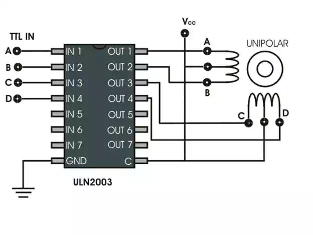
Power Supply for Stepper Motor Drive
A stepper motor may run at voltages varying from 5 V to 12 V and similarly the current draw will be somewhere in the range of 100 mA to 400 mA. The motor specifications will be given by the supplier, accordingly we must design the supply. It is important that the power must be regulated so that fluctuations in speed and torque can be avoided.
Power Supply Unit
The above image shows an example power supply unit. Since 7812 voltage regulator can handle only up to 1A of current, an outboard transistor is used here. It can handle 5 A of current. Proper heat sink must be provided depending on the total current draw.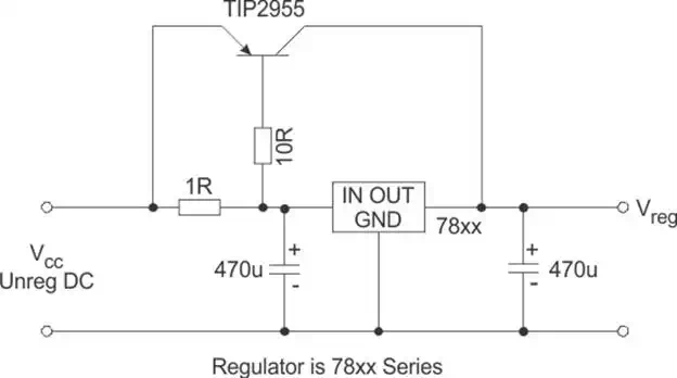
The above block diagram shows the flow of connections and the interconnections between the various components on the driver board.
Comprehensive Stepper Motor Drive
The stepper motor drive is a dumb piece of electronics unless and until you program the microcontroller to give signals correctly to the stepper motor via the driver. A stepper motor can operate in many modes like full step, wave drive or half stepping (Please refer the article on Stepper Motor for the sequence of steps).Hence, we must make the driver interactive enough to be able to take command from the user and do the required kind of stepping. Also, we must control the speed of rotation. A start/stop command must start or stop the motor rotation.
To accomplish the above functions, we need to use additional pins on the micro-controller. Two pins are required to select the kind of stepping and to start or stop the motor. One pin is required to connect a pot which will act as a speed controller. The ADC inside the micro-controller will be used to control the speed of rotation.
Program Algorithm
1. Initialize the port pins in input / output modes.
2. Initialize the ADC module.
3. Create separate functions for half stepping, full stepping and wave drive and for delay.
4. Check two port pins for operating mode (00-stop, 01-wave drive,10-full step, 11-half stepping).
5. Go to the appropriate function.
6. Read the Potentiometer value via the ADC and accordingly set a delay value.
7. Complete one cycle of sequence.
8. Go to step 4.
If you plan to make your own board using CAD software like EAGLE, make sure that you provide sufficient thickness for the motor currents to flow without heating the board too much. Also, as motors are inductive components, care must be taken so that they must not disturb the other signal paths by way of interferences. Proper ERC and DRC checks must be followed.
Note-
Building a Stepper motor driver is more about selecting the proper power supply and driver and the selection of the micro-controller is secondary. A lot of micro-controllers can do the simple job of rotating the motor, but it is the design considerations regarding the voltages and currents that you must focus on while designing the driver. Also, a single driver board must be able to handle voltages and currents over a wide range and not only for a single motor. This will enable you to use the same board in a large number of different projects rather than making a new one every time.