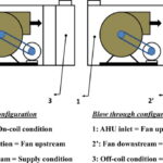
We have learnt that when both the RSHF and GSHF ratio lines are plotted on the psychrometric chart, the intersection of the two lines represents the condition of the supply air to the space. It is also the condition of the air leaving the apparatus. However this neglects fan and duct heat gain, duct leakage losses, etc. In actual practice, these heat gains are taken into account in estimating the cooling load. Therefore, the temperature of the air leaving the apparatus is not necessarily equal to the temperature of the air supplied to the space. For a draw-through arrangement, that is with the supply fan past the cooling coil- The supply air temperature will be greater than the “coil leaving” temperature, because of the heat added by the fan work.

For this example if a 5hp motor is required, the temperature rise will be:

Where
P is the power rating in hp and 2545 is Btu/hp
∆T = 2.1ºF
Thus the actual coil leaving condition shall be 58 – 2.1 = 55.9ºF DB which should be plotted on the chart.
For a blow-through arrangement, the fan work causes an increase in the mixed-air temperature before the air goes through the cooling coil, and the process is as in figure below. For this case, it is necessary to increase the supply of air ∆T to 22ºF to get a valid “coil leaving” condition. This will reduce the air quantity to 5050 cfm and will require more care in the air distribution system to avoid cold air spillage and drafts. The ∆w will be greater due to the reduction in cfm. Humidity control is not always required, but some upper limit will be inherent in any refrigeration-type cooling process-chilled water, brine, or direct expansion.