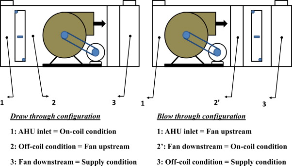
Summarizing, draw-through units typically require 10% more supply air than blow through systems for the same temperature off the cooling coil. This will increase duct size and fan operating cost. The fan heat will ensure the supply air is not fully saturated, avoiding moisture issues.
Blow-through units add the fan heat (usually equivalent to 2-3°F) before the cooling coil. The leaving air temperature from the cooling coil then becomes the supply air temperature. This provides the maximum temperature rise between the cooling air and the space design temperature (or the least amount of supply air will be required). Since the air is often fully saturated and moisture may be an issue, blow-through should not be used with final filters downstream of the coils.
COOLING COIL CAPACITY
A cooling coil serving one or more conditioned spaces is sized to meet the highest sum of the instantaneous space loads for all the spaces served by the coil, plus any external loads such as fan heat gain, duct heat gain, duct air leakage, and outdoor air ventilation loads (sensible and latent). At design condition, a cooling coil provides design air flow at design off-coil air temperature and humidity, which are determined to meet each zone’s temperature and humidity requirements. For dehumidification applications, the cooling coil should have adequate latent cooling capacity as well as sensible cooling capacity.
Find below a simple cooling system:

The nodes description is as follows:
1. The outside air conditions are located at point “o” in figure above.
2. The coil leaving conditions are located at point 1.
3. The supply air conditions are located at point 2 (note with the arrangement depicted, supply fan motor heat is added to the air stream)
4. The inside air conditions are located at point 3.
5. The mass flow rate of return air is located at point 4 ( temperature conditions are essentially similar to point 5, but the mass flow rate varies depending on what portion of return air will be exhausted)
6. The mixture conditions are located at point 5 (note proportion of return air and outdoor air are mixed)
Plotting these nodes on the psychrometric chart:

The room air flow is given by equation:
CFM = RSH / [1.08 x (T 3 – T 2)]
Normally, zone air flow is calculated based on design sensible loads and design supply air flow, which may not meet humidity requirements. For dehumidification applications, the design air flow must meet both temperature and humidity requirements. A psychometric chart is used to determine the enthalpy at point 5 and point 2 and the mass flow rate at point 1. The total cooling coil load is calculated by the following equation:
Q coil = m1 * (h5– h2) or
Empirically
Q coil = 4.5 x CFM x (h5-h2)
Where:
• m1 is the mass flow rate at point 1
• h5 is the enthalpy at point 5
• h2 is the enthalpy at point 2